
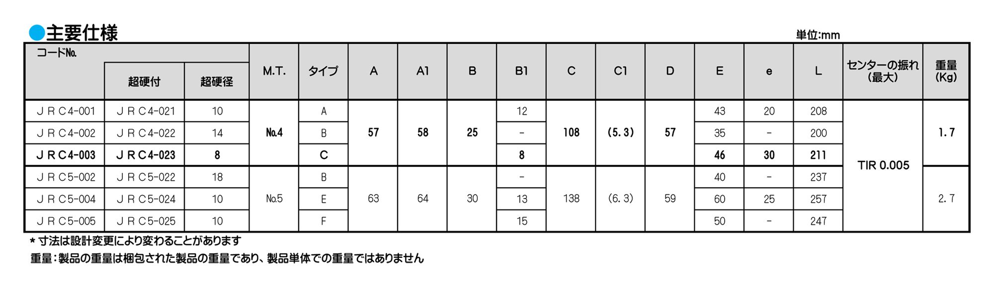
![]()
ローリングセンター
ワークドライビングセンター
傘型回転センター
レースセンター
情報・その他資料
情報・その他

是非、ご覧ください


ローリングセンター
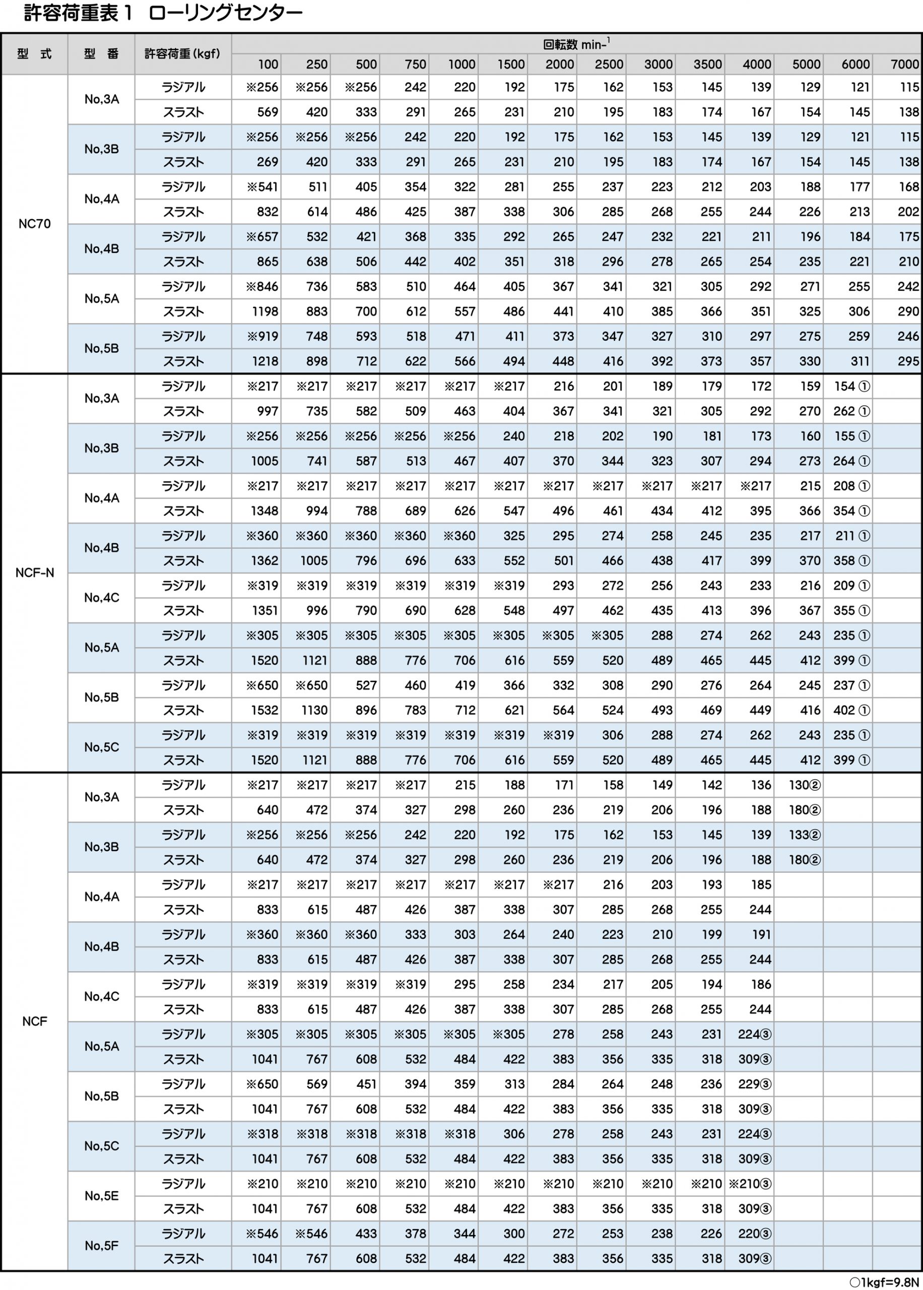
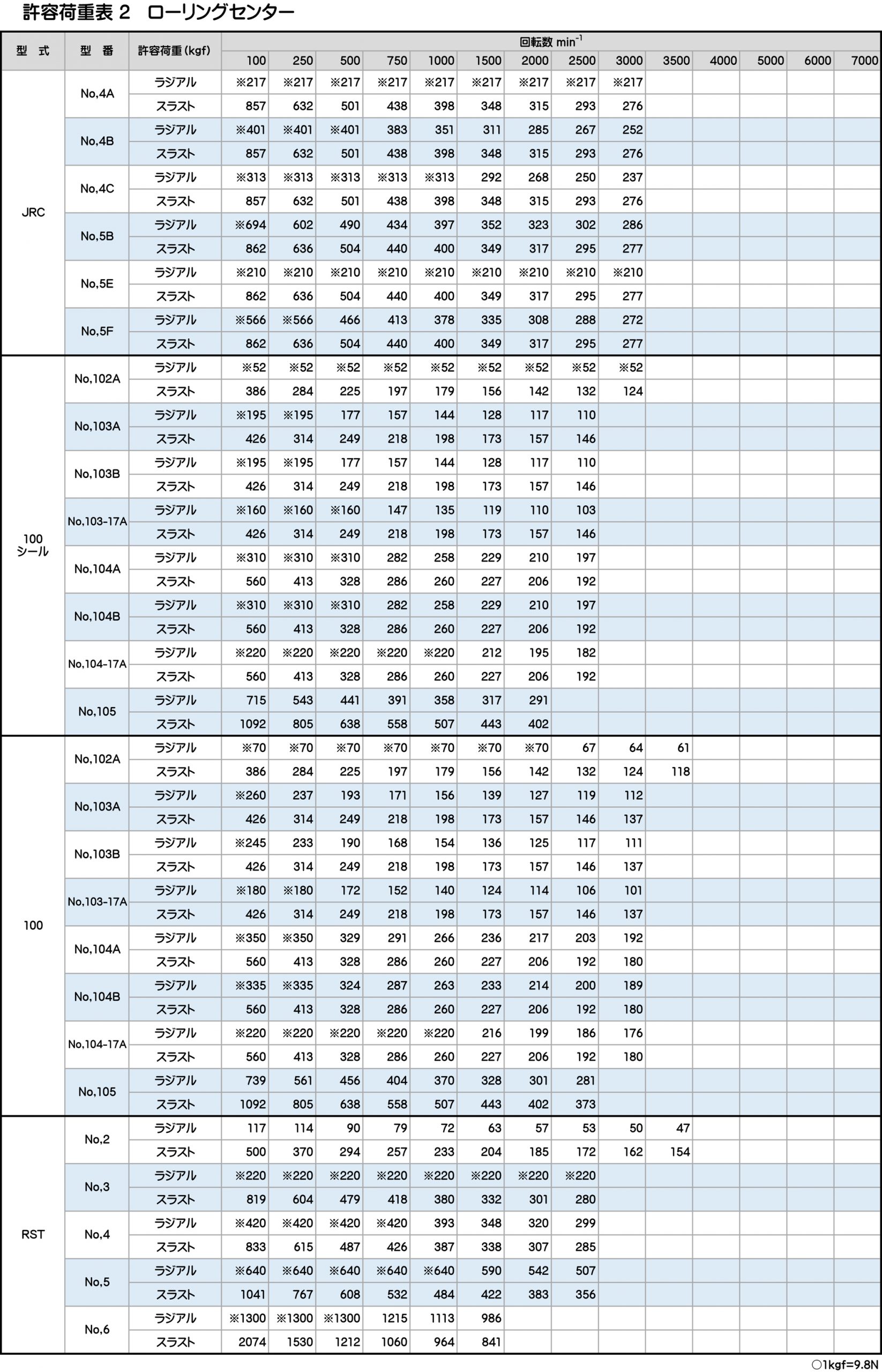
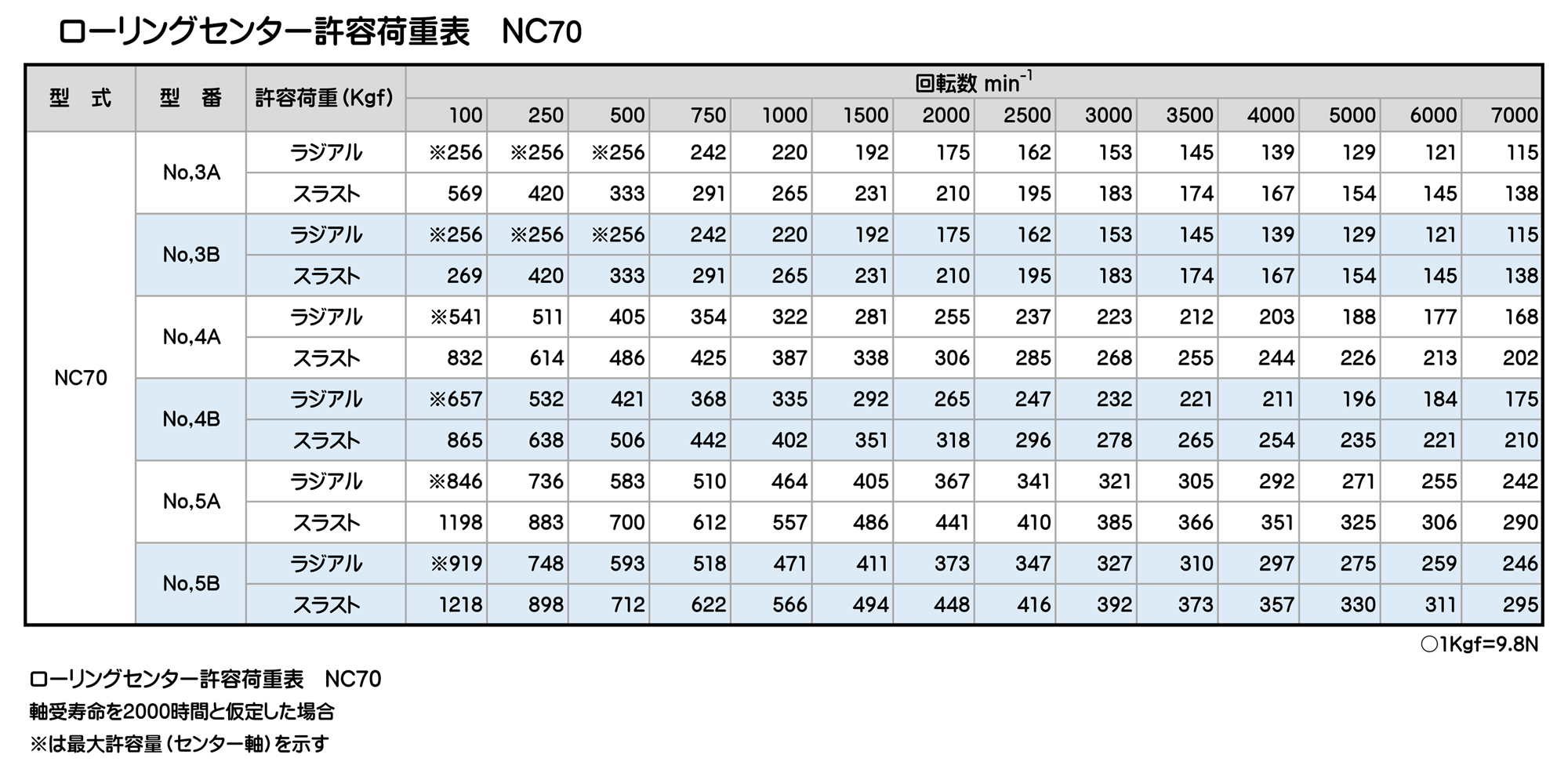
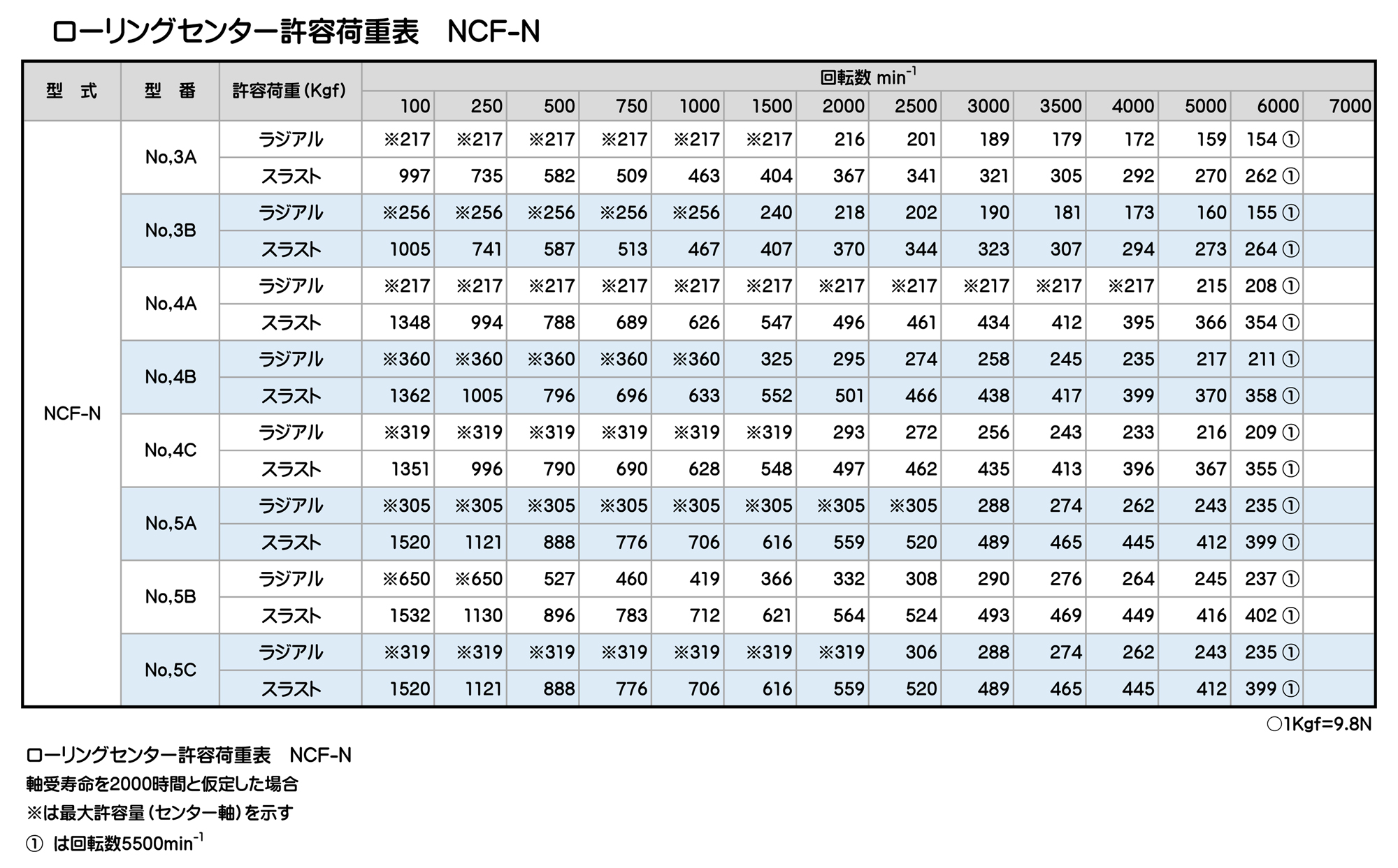
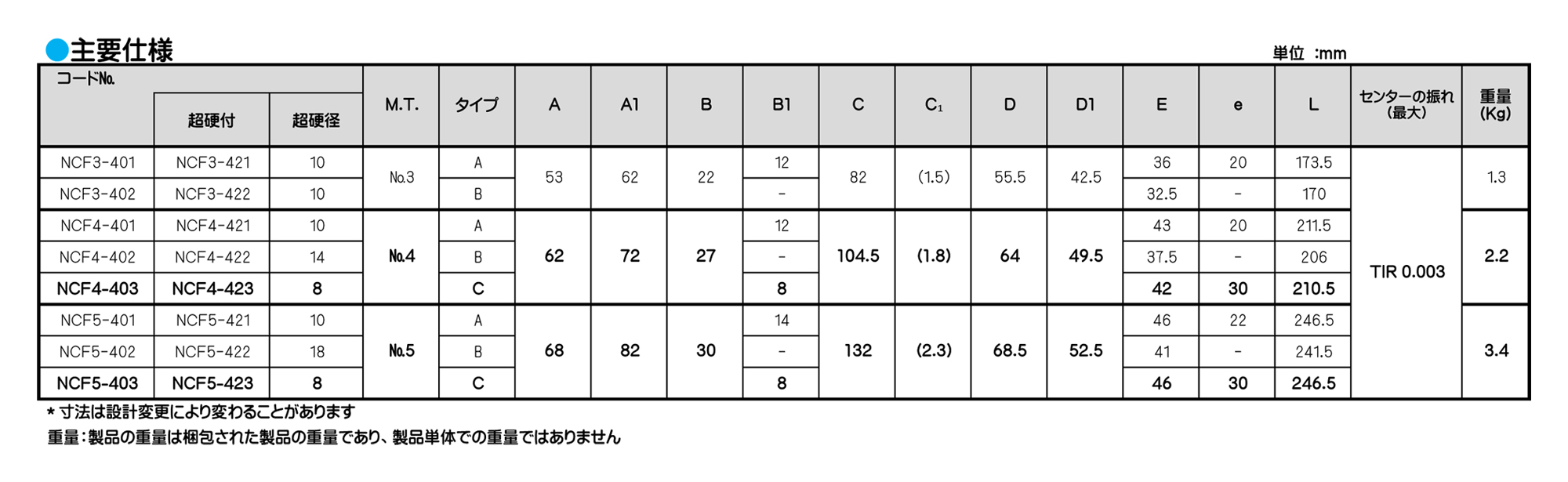
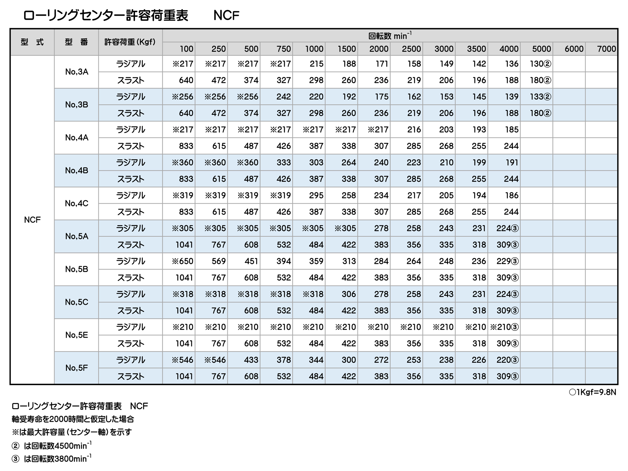
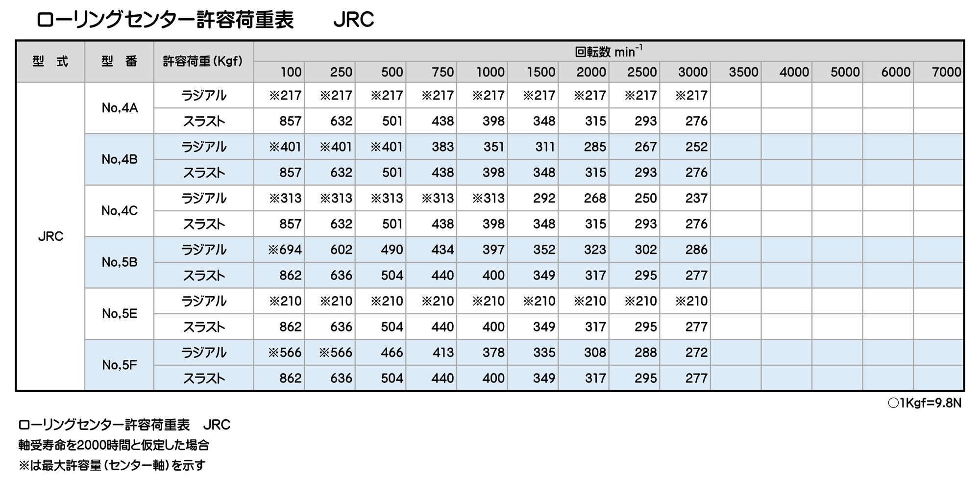
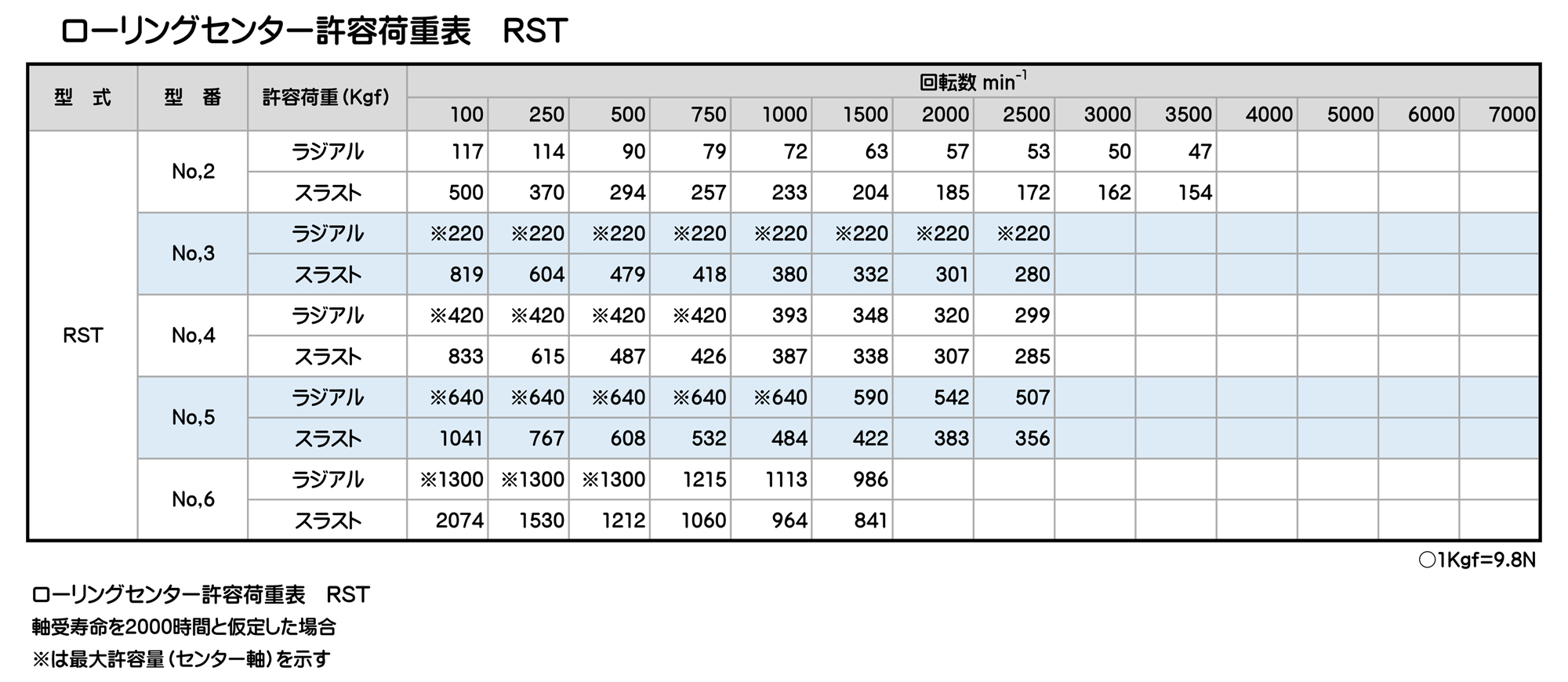
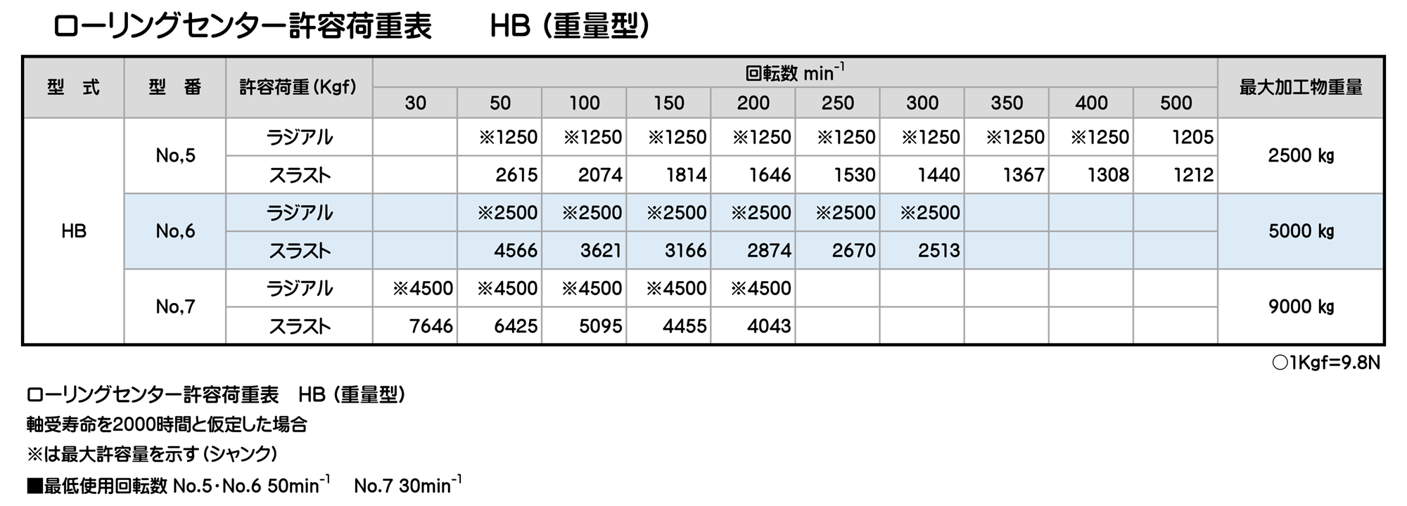
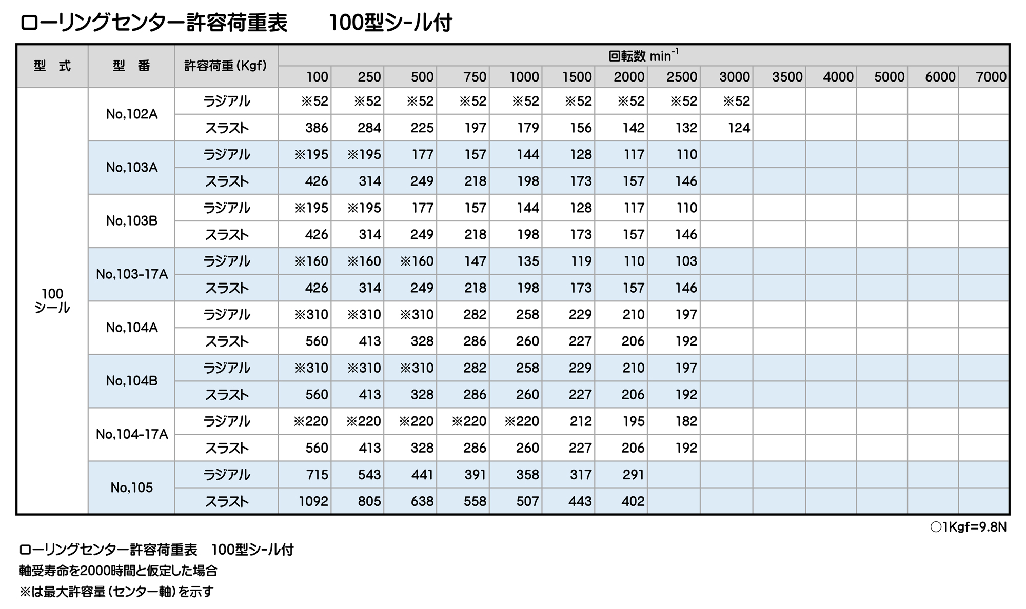
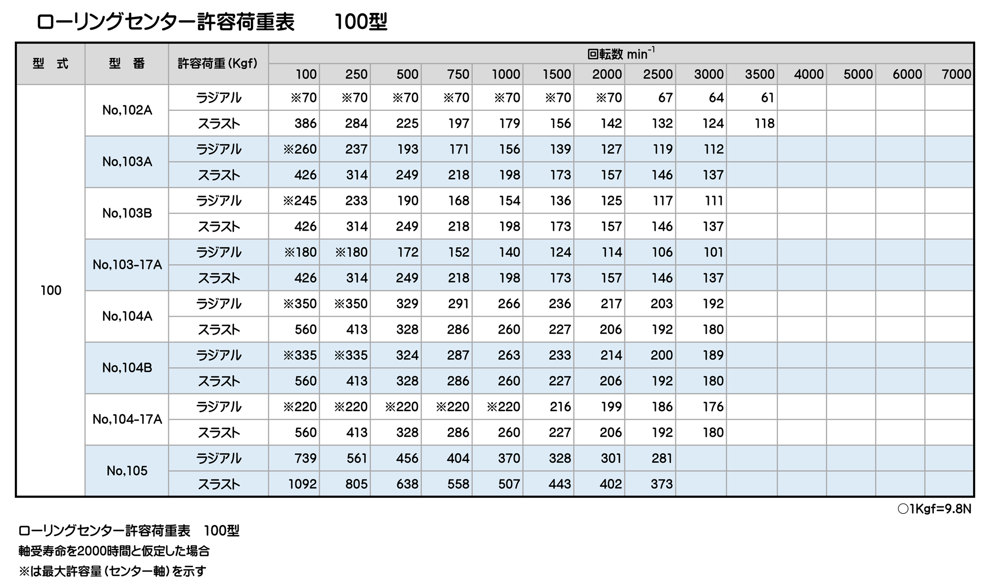
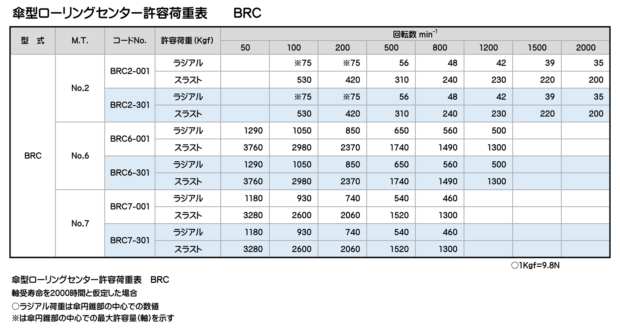
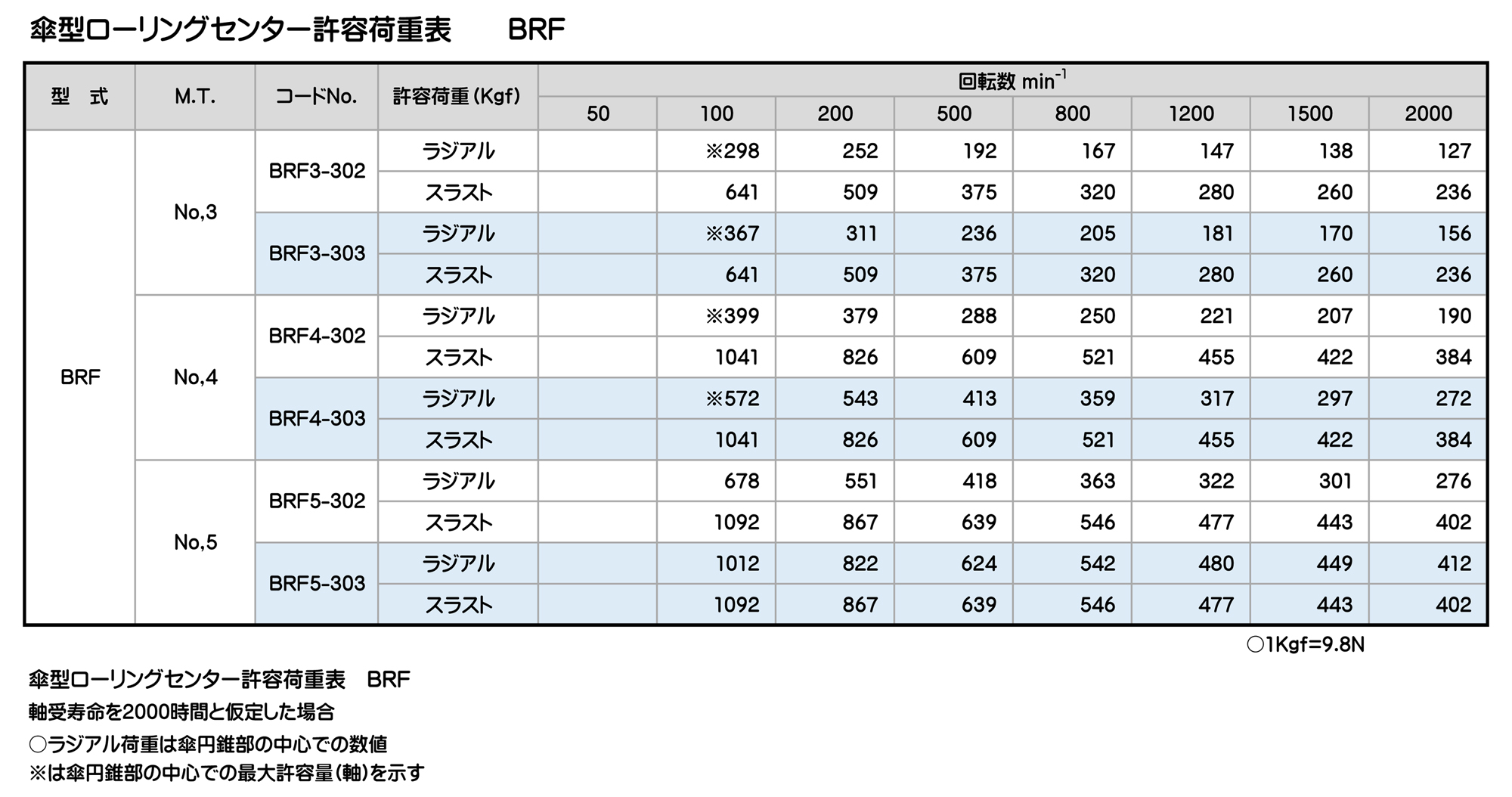
ローリングセンター許容荷重表
軸受寿命を2000時間と仮定した場合
※は最大許容量(センター軸)を示す
① は回転数5500min-1
② は回転数4500min-1
③ は回転数3800min-1
ローリングセンター
ローリングセンター

ローリングセンター
ローリングセンター
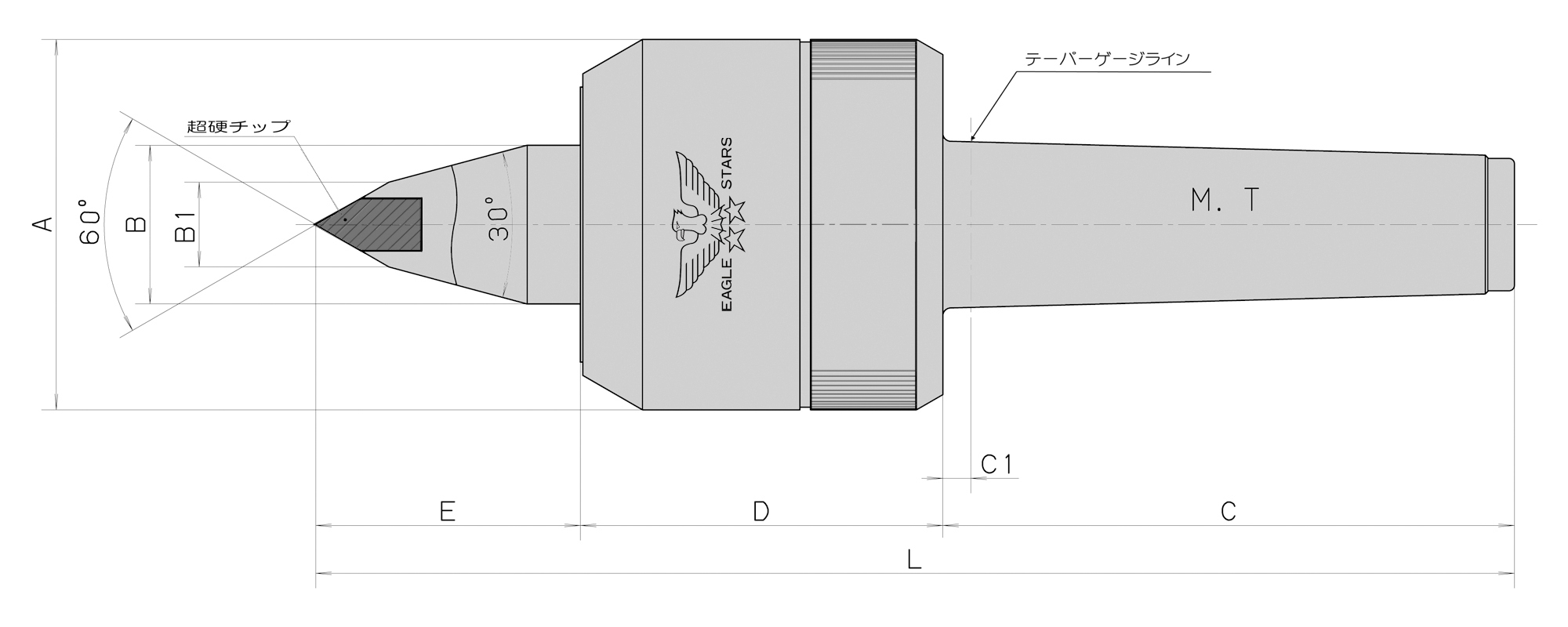

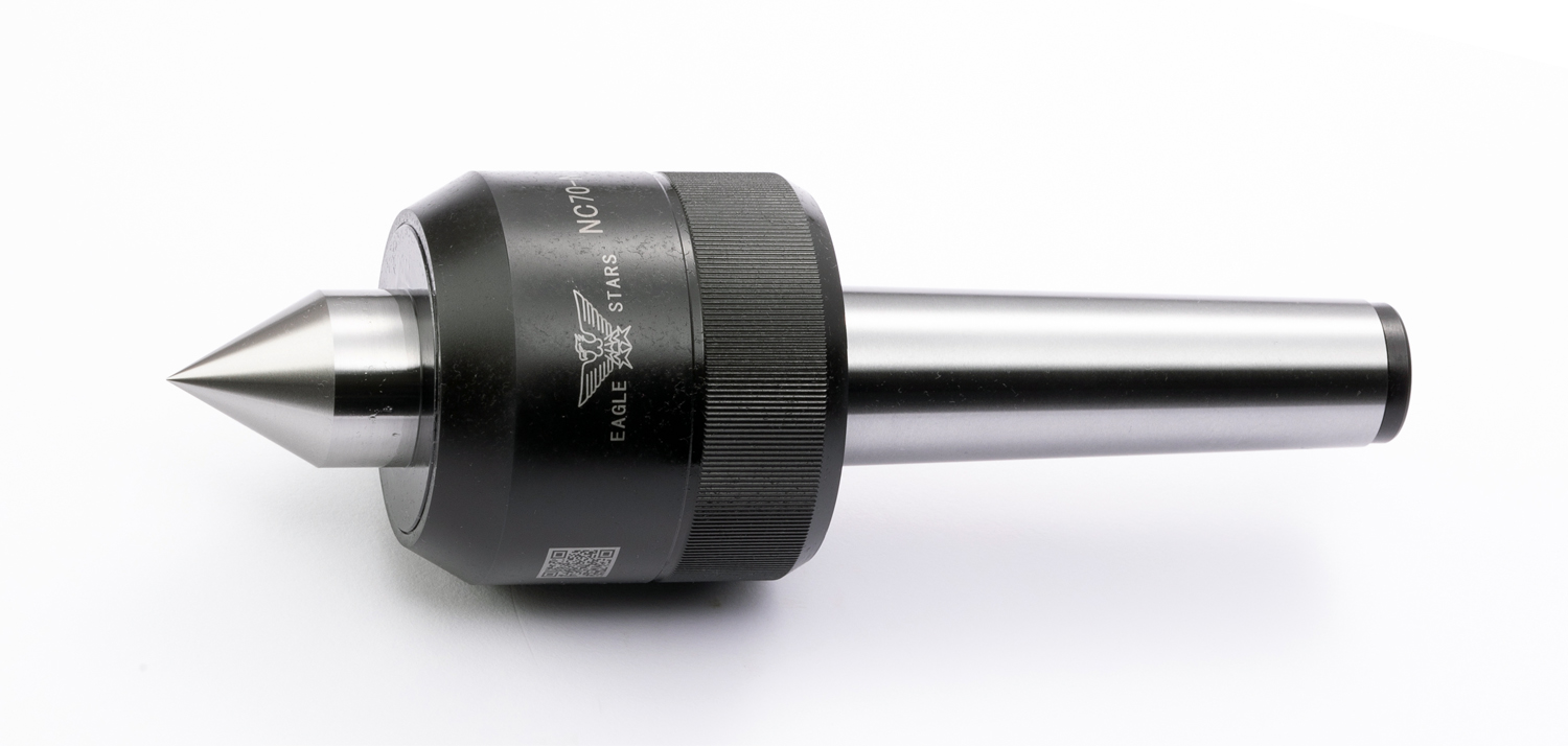
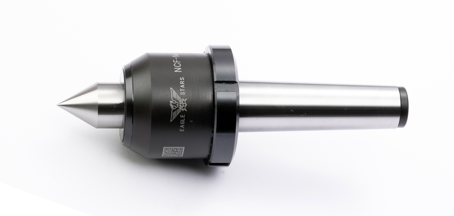
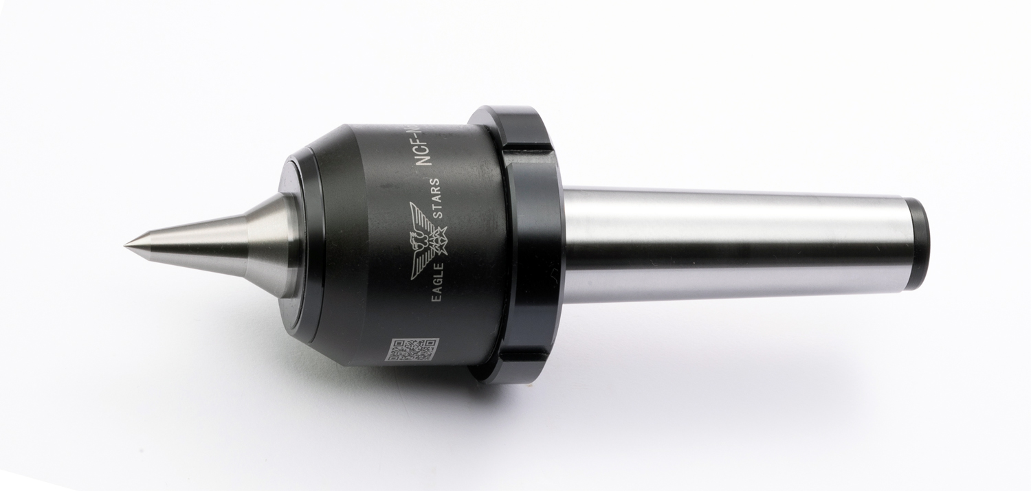
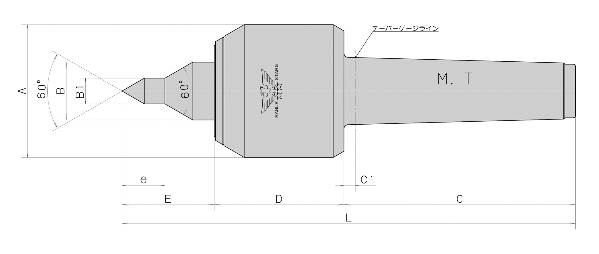
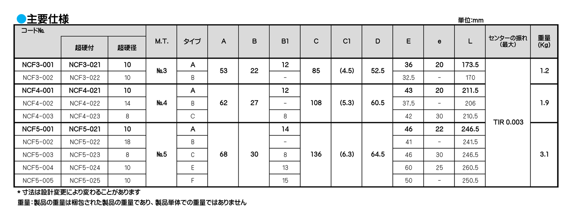
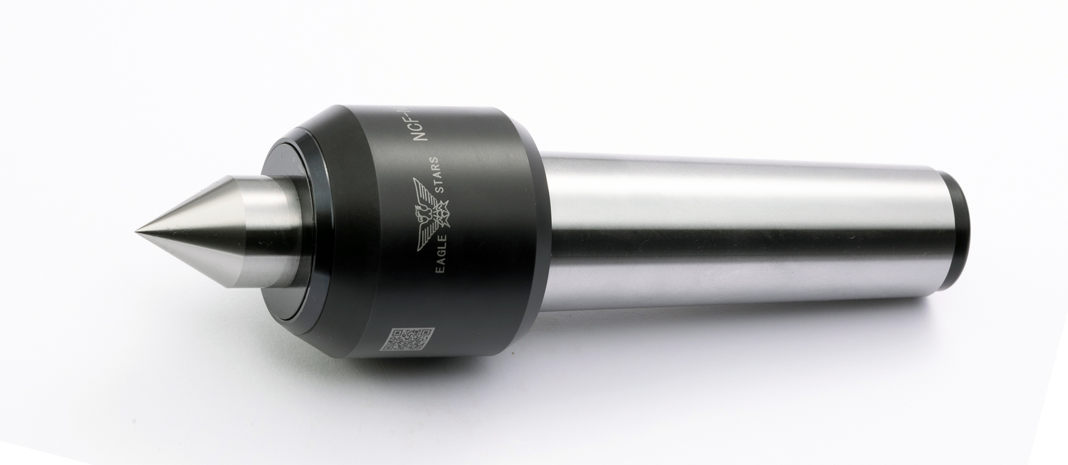
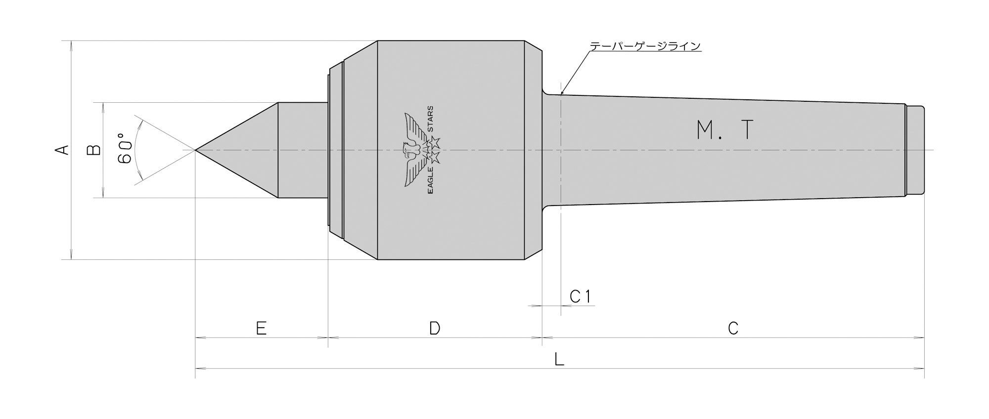
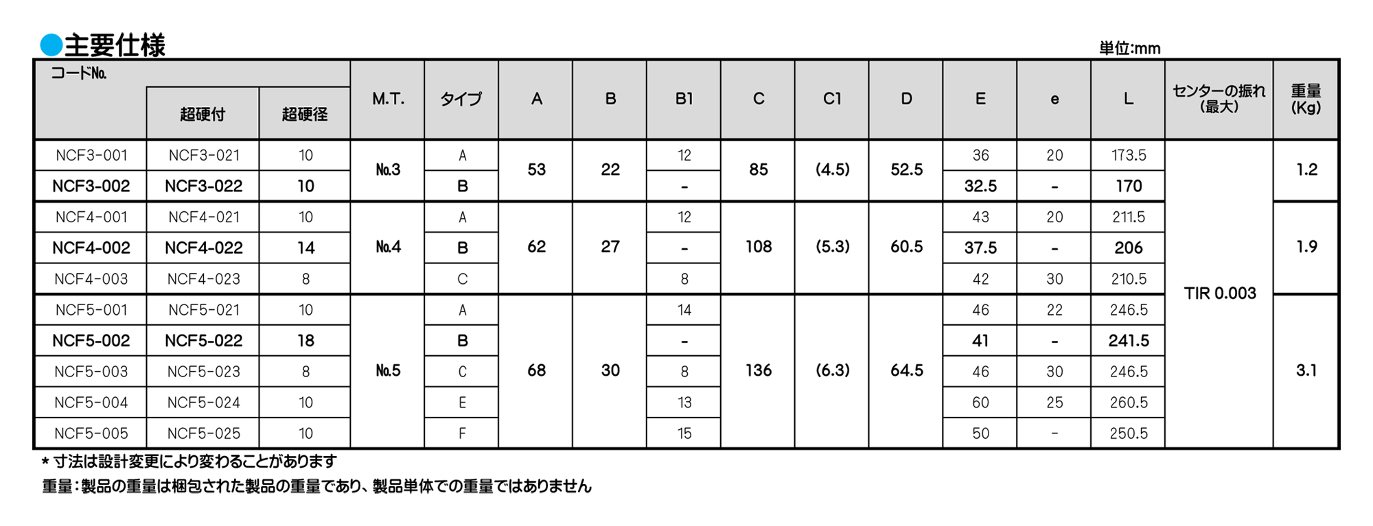
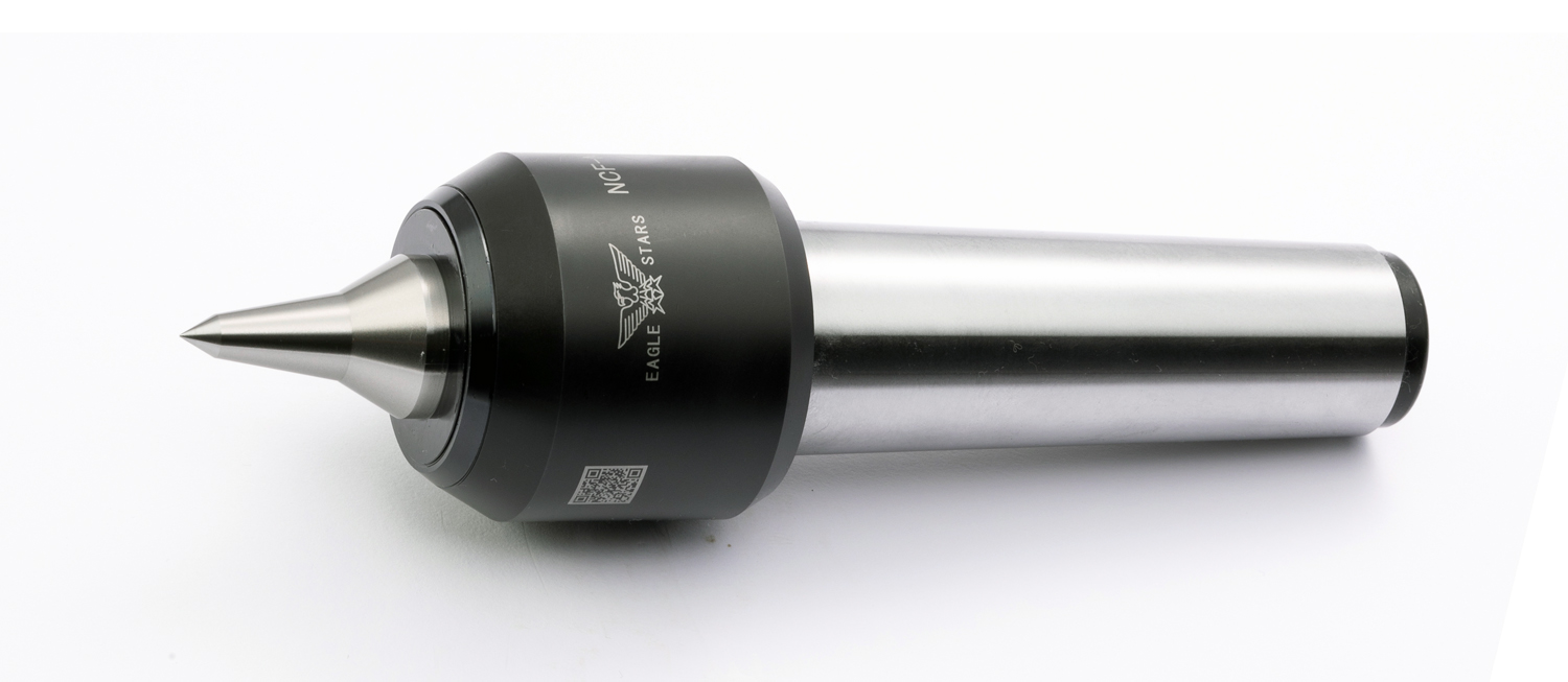
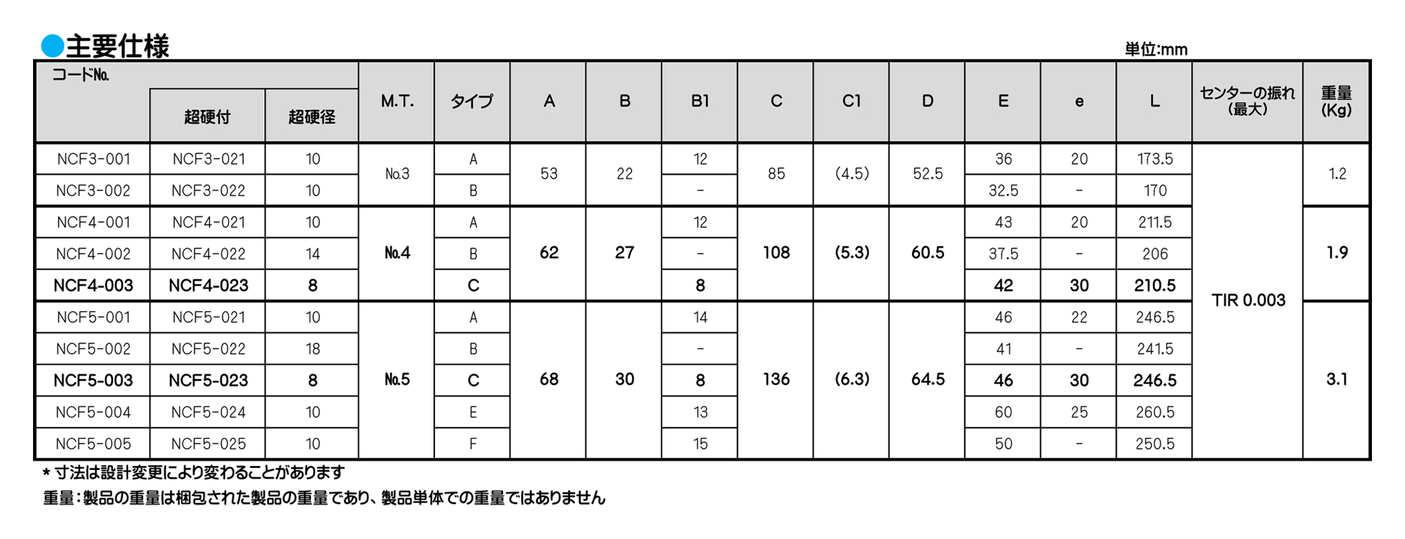
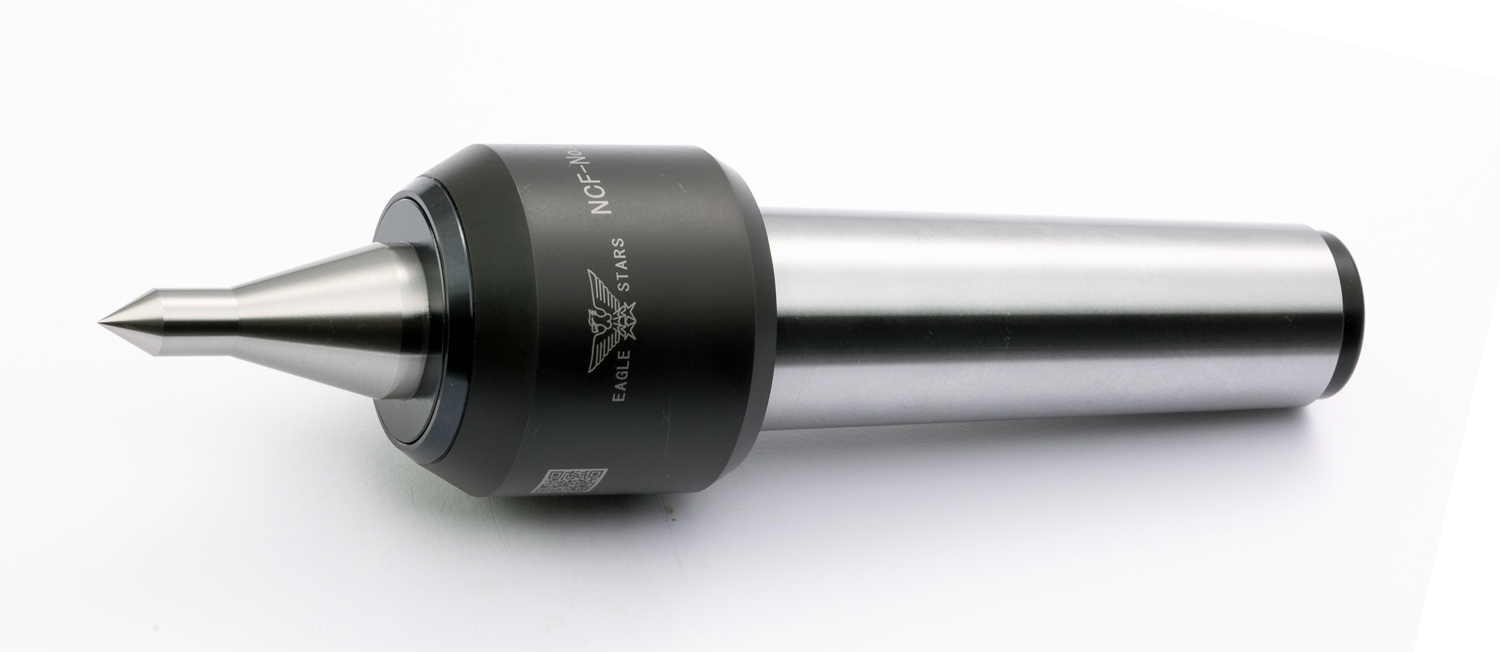
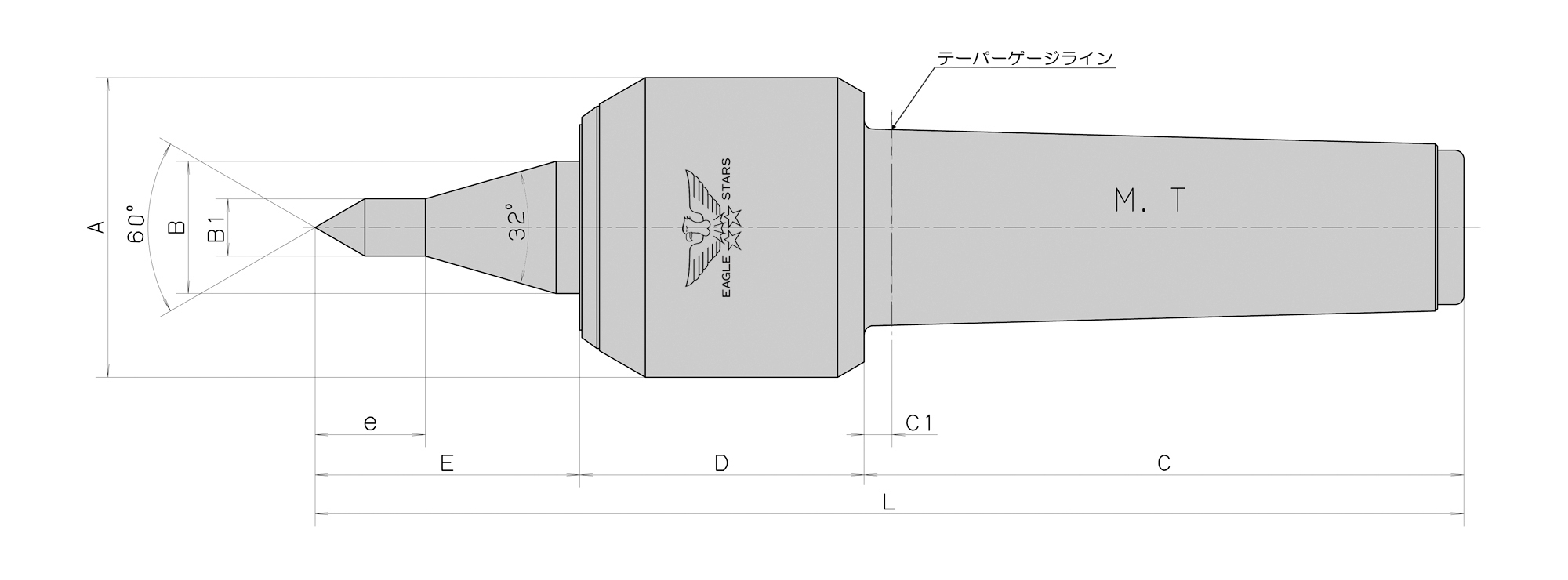
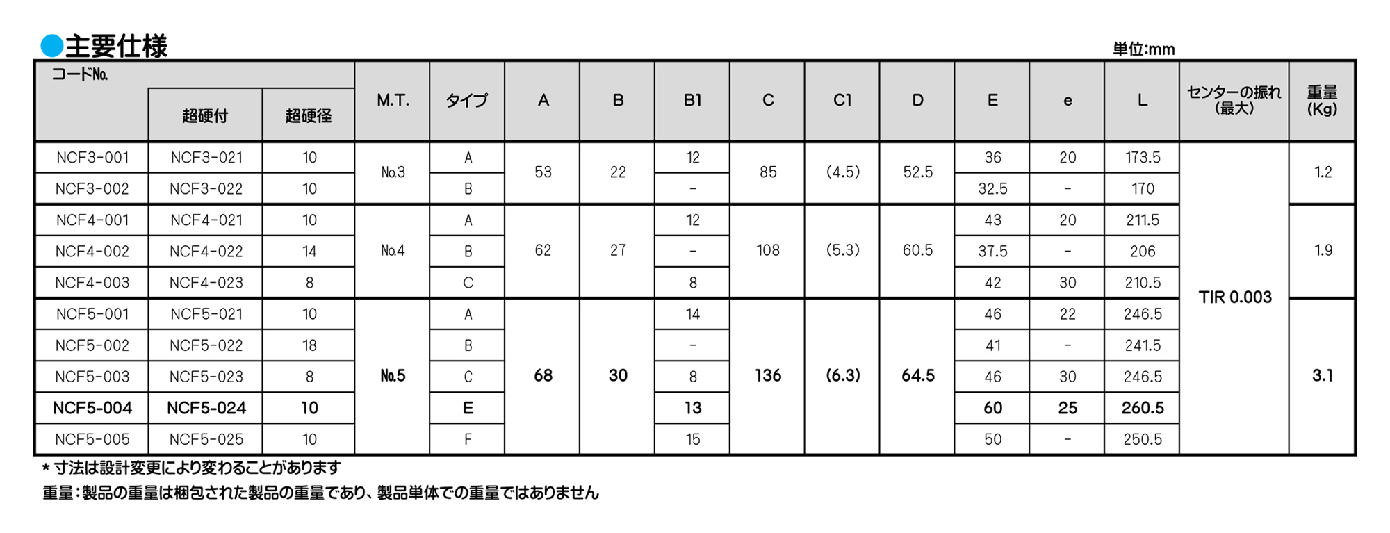
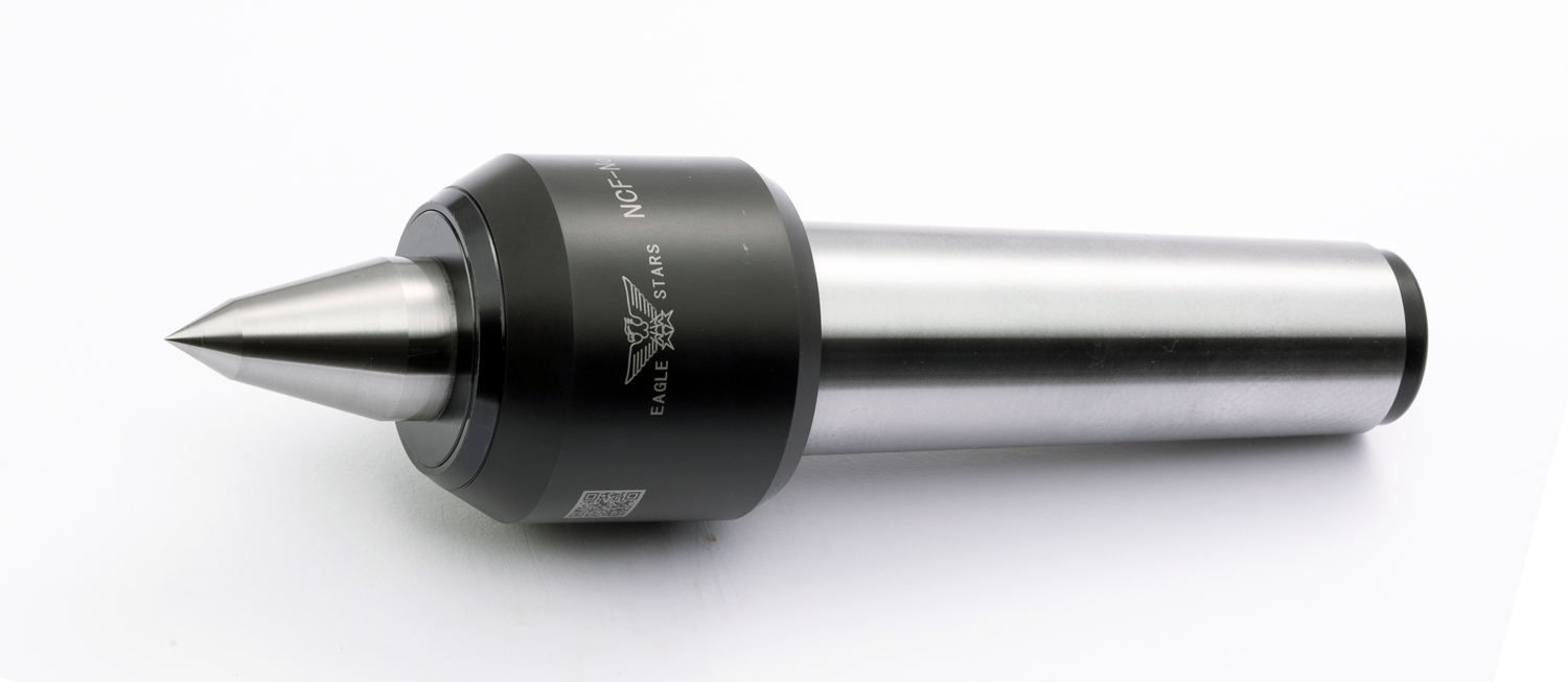
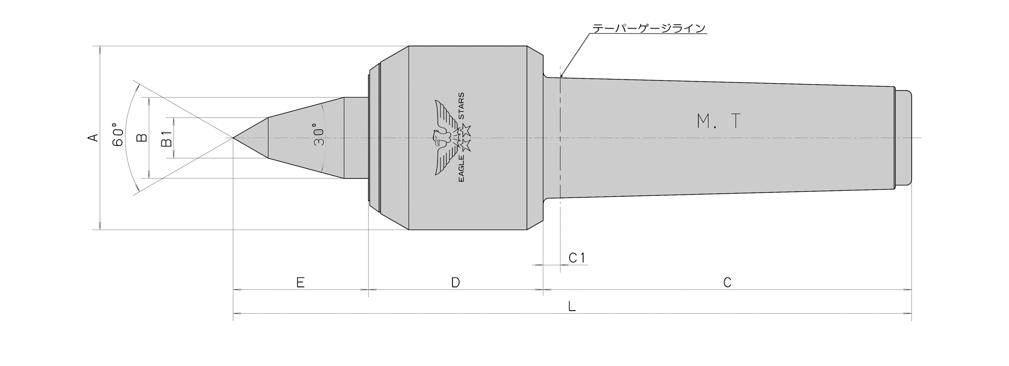
■超高速回転(7000min-1)高精度(TIR 0.003)を主眼として設計されています。
■超高速回転による摩耗、摩擦にも耐えるよう先端部に超硬チップを付けてあります。(A型)
■本製品の内部には組み合わせアンギュラベアリング(3ヶ)、ニードルベアリングの2種類のベアリングを使用し、剛性に耐えるよう細心の設計、組立をされています。
■切削油使用の場合の防浸対策には独自のラビリンス機構(非接触)を採用した事により摩耗、摩擦、動力損失がなく本機の温度上昇が少なくなり精度、寿命時間の信頼性を高めました。
◆研削盤又は1000min-1以下でご使用の場合にはVシール仕様になります。オプションでの対応になりますので、ご指示ください。
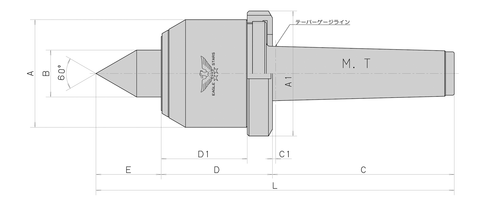
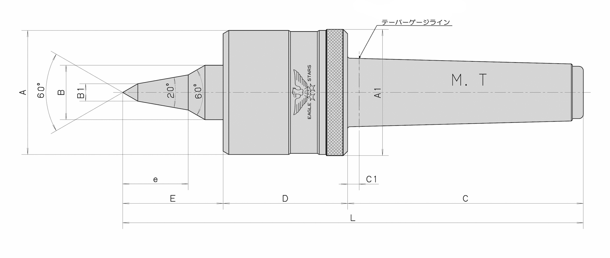
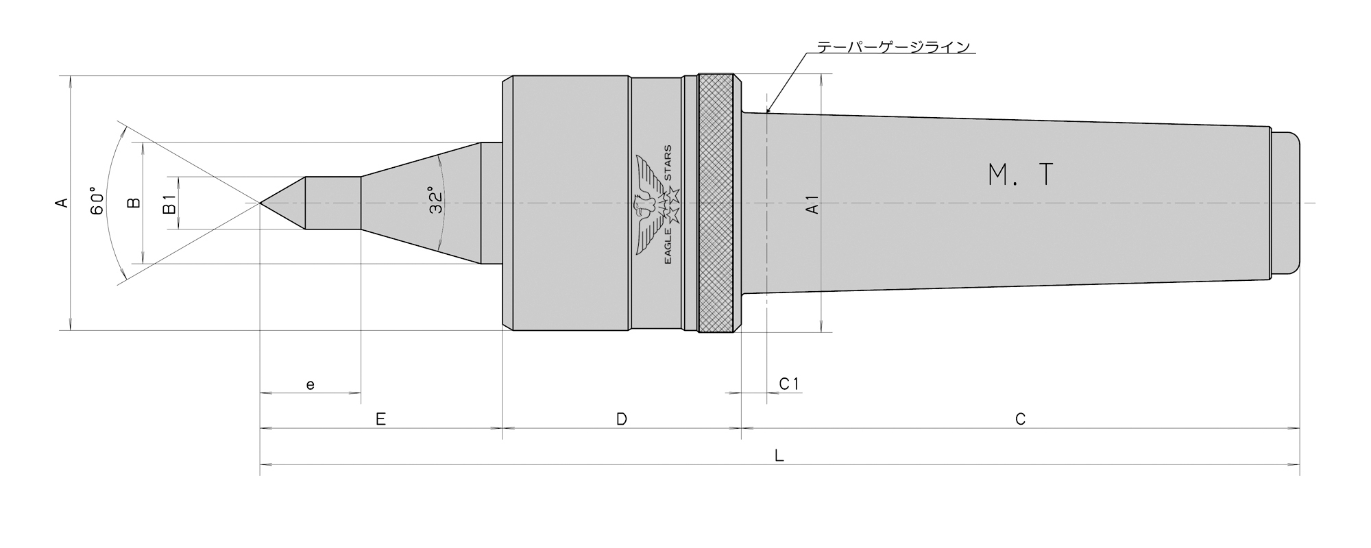
◆研削盤によっては、テーパー基準の位置がテーパ穴の奥になっている場合があります。この場合は、C1寸法を長くした特殊本体仕様になりますのでご指示下さい。納期、価格についてはご指定のルートよりお見積もりさせていただきます。
ローリングセンター
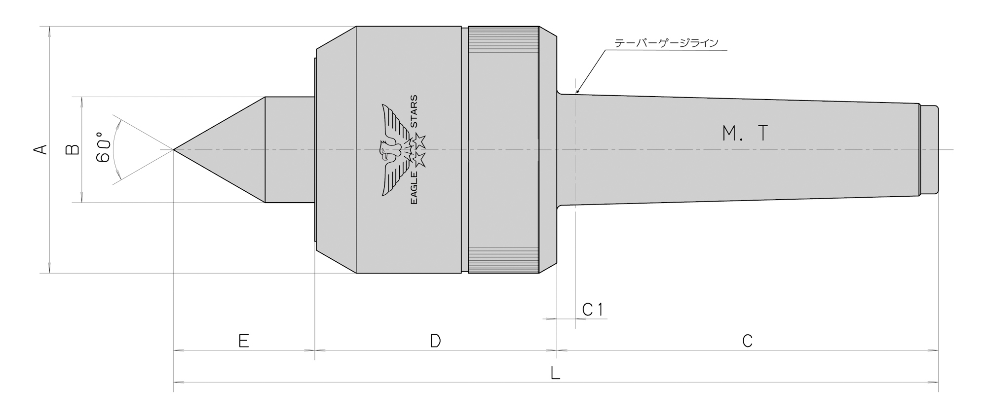
■超高速回転(7000min-1)高精度(TIR 0.003)を主眼として設計されています。
■超高速回転による摩耗、摩擦にも耐えるよう先端部に超硬チップを付けてあります。(A型)
■本製品の内部には組み合わせアンギュラベアリング(3ヶ)、ニードルベアリングの2種類のベアリングを使用し、剛性に耐えるよう細心の設計、組立をされています。
■切削油使用の場合の防浸対策には独自のラビリンス機構(非接触)を採用した事により摩耗、摩擦、動力損失がなく本機の温度上昇が少なくなり精度、寿命時間の信頼性を高めました。
◆研削盤又は1000min-1以下でご使用の場合にはVシール仕様になります。オプションでの対応になりますので、ご指示ください。
◆研削盤によっては、テーパー基準の位置がテーパ穴の奥になっている場合があります。この場合は、C1寸法を長くした特殊本体仕様になりますのでご指示下さい。納期、価格についてはご指定のルートよりお見積もりさせていただきます。
ローリングセンター
ローリングセンター
■最高回転数 5500min-1
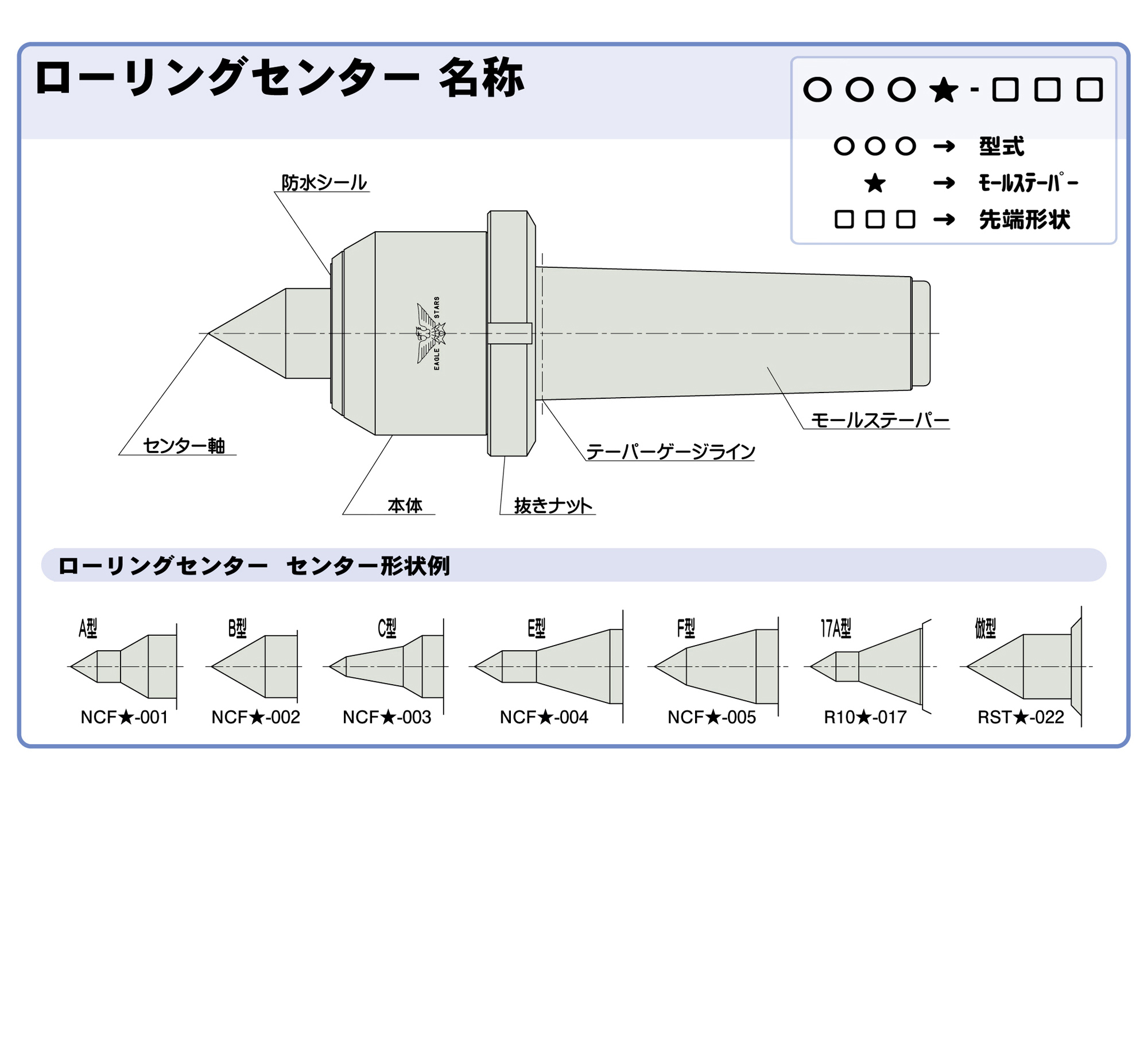
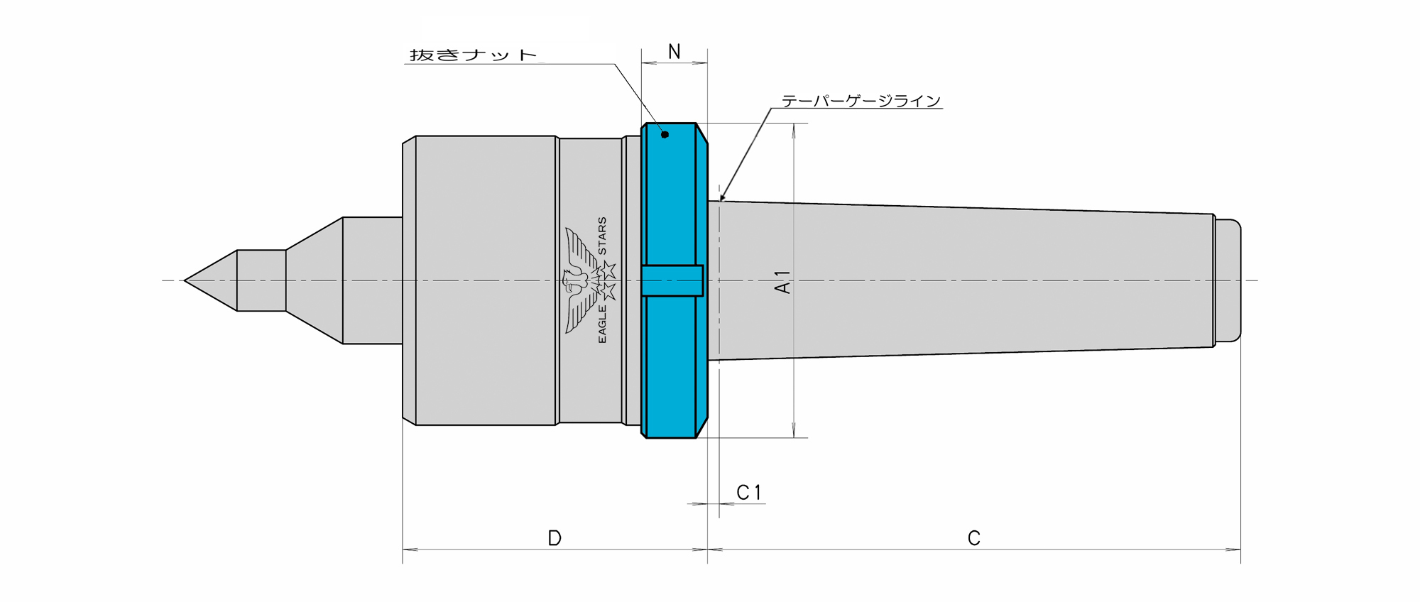
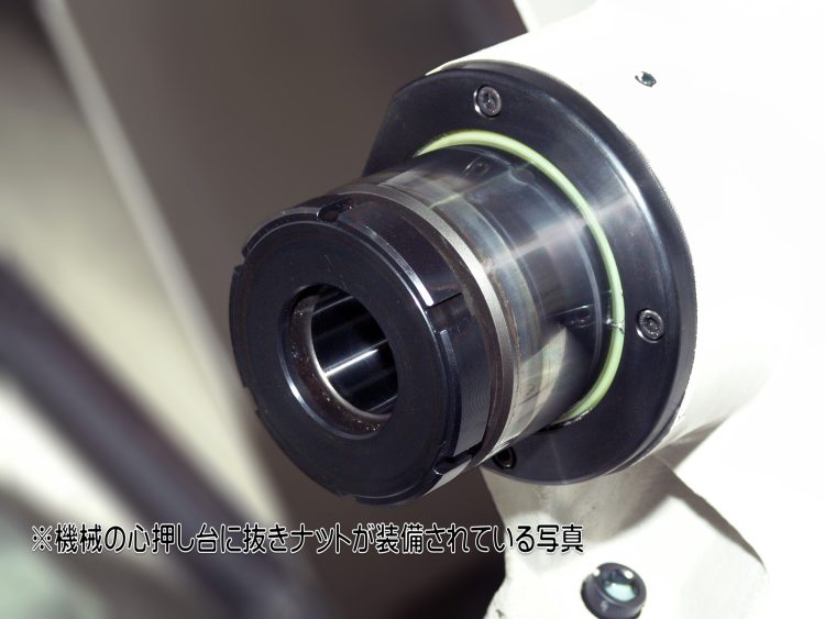
■本体後部に抜きナットを装備し、芯押し台の前部からの取り外しを可能にしております。
■本製品の内部には組み合わせアンギュラベアリング(3ケ)、ニードルベアリングを使用しており回転トルクがスムーズです。
■A型、C型は細物タイプでネジ切り、端面加工に最適です。
■切削油使用の場合の防浸対策には独自のラビリンス機構(非接触)を採用した事により摩耗、摩擦、動力損失がなく本機の温度上昇が少なくなり精度、寿命時間の信頼性を高めました。
■スラスト荷重に対して耐えるよう設計されているため弊社製品ワークドライビングセンターをご使用される場合には特にご使用をおすすめいたします。
◆研削盤又は1000min-1以下でご使用の場合にはVシール仕様になります。オプションでの対応になりますので、ご指示ください。
◆研削盤によっては、テーパー基準の位置がテーパ穴の奥になっている場合があります。この場合は、C1寸法を長くした特殊本体仕様になりますのでご指示下さい。納期、価格についてはご指定のルートよりお見積もりさせていただきます。
ご使用について
■構造上、センター軸に対して無負荷の場合センター軸が0.5mm程度前後します。使用時には推力をかけてご使用ください。
ローリングセンター
■最高回転数 5500min-1
■本体後部に抜きナットを装備し、芯押し台の前部からの取り外しを可能にしております。
■本製品の内部には組み合わせアンギュラベアリング(3ケ)、ニードルベアリングを使用しており回転トルクがスムーズです。
■A型、C型は細物タイプでネジ切り、端面加工に最適です。
■切削油使用の場合の防浸対策には独自のラビリンス機構(非接触)を採用した事により摩耗、摩擦、動力損失がなく本機の温度上昇が少なくなり精度、寿命時間の信頼性を高めました。
■スラスト荷重に対して耐えるよう設計されているため弊社製品ワークドライビングセンターをご使用される場合には特にご使用をおすすめいたします。
◆研削盤又は1000min-1以下でご使用の場合にはVシール仕様になります。オプションでの対応になりますので、ご指示ください。
◆研削盤によっては、テーパー基準の位置がテーパ穴の奥になっている場合があります。この場合は、C1寸法を長くした特殊本体仕様になりますのでご指示下さい。納期、価格についてはご指定のルートよりお見積もりさせていただきます。
ご使用について
■構造上、センター軸に対して無負荷の場合センター軸が0.5mm程度前後します。使用時には推力をかけてご使用ください。
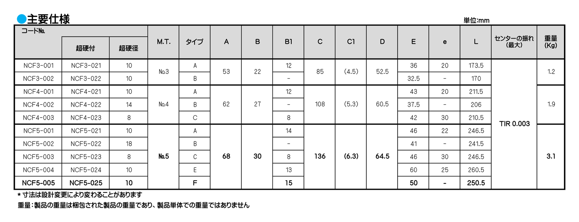
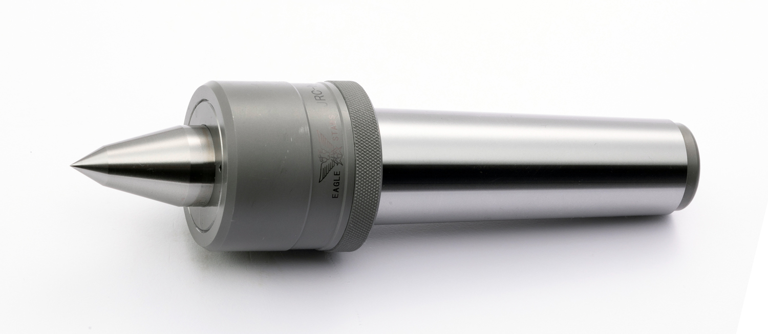
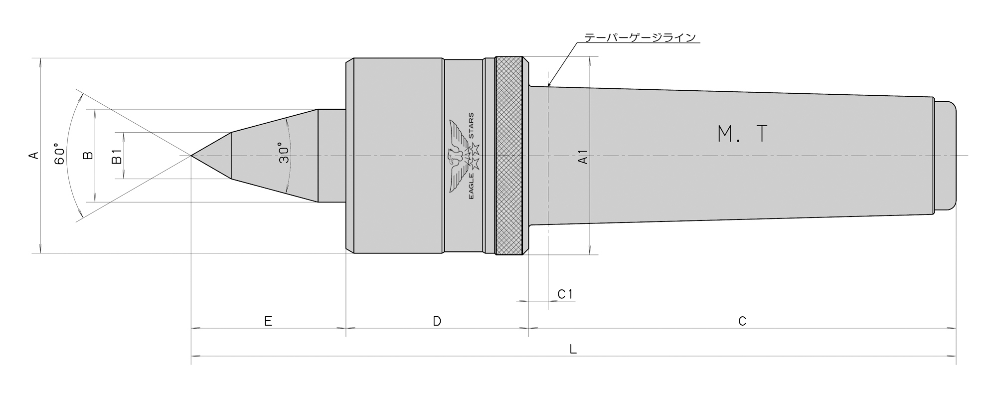
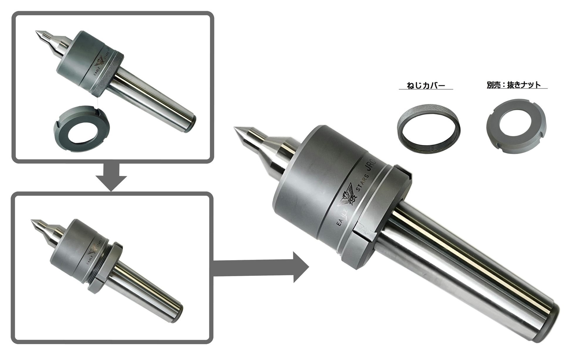
ローリングセンター
ローリングセンター
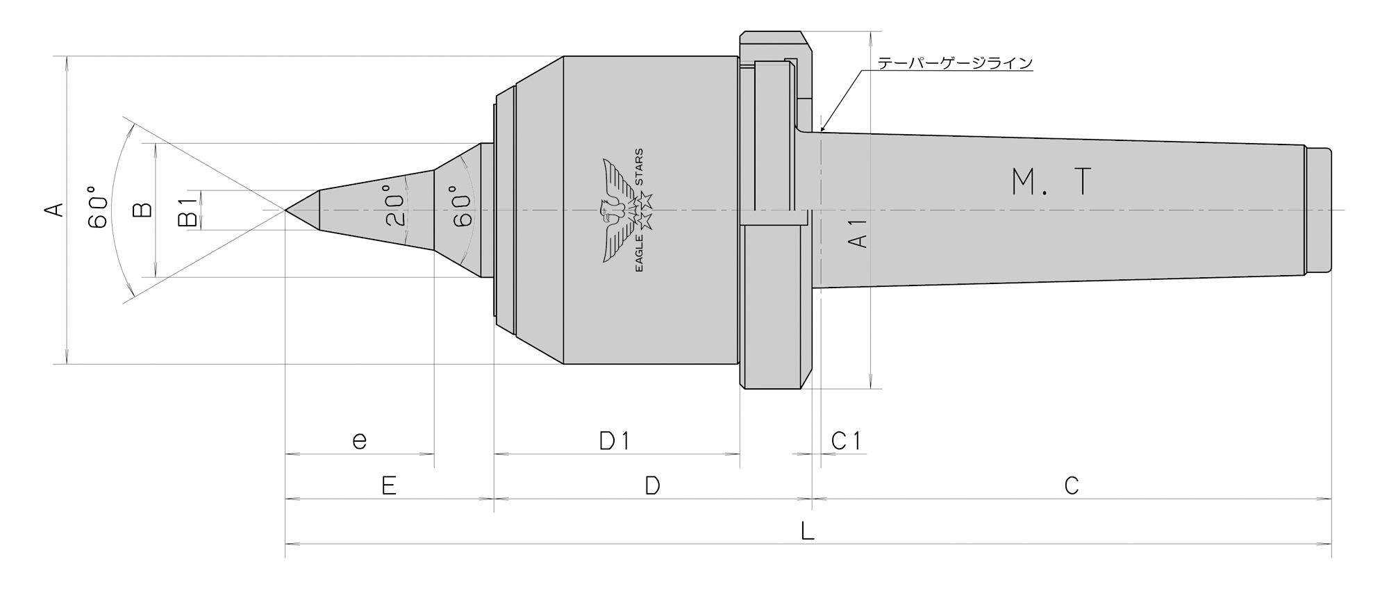
■最高回転数 (min-1) No.3=4500/No.4=4000/No.5=3800
■本製品にはアンギュラベアリング、スラストベアリング、ニードルベアリングを使用しており、回転トルクがスムーズです。
■A型、C型、E型は細物タイプでネジ切り、端面加工に最適です。
■切削油使用の場合の防浸対策には独自のラビリンス機構(非接触)を採用した事により摩耗、摩擦、動力損失がなく本機の温度上昇が少なくなり精度、寿命時間の信頼性を高めました。
◆研削盤又は1000min-1以下でご使用の場合にはVシール仕様になります。オプションでの対応になりますので、ご指示ください。
◆研削盤によっては、テーパー基準の位置がテーパ穴の奥になっている場合があります。この場合は、C1寸法を長くした特殊本体仕様になりますのでご指示ください。納期、価格についてはご指定のルートよりお見積もりさせていただきます。
ローリングセンター
ローリングセンター

■最高回転数 3000min-1
■テーパローラベアリング仕様で、スムーズな低トルク設計
■本体はコンパクトで使いやすい回転領域(500min-1〜3000min-1)
■シールを標準搭載
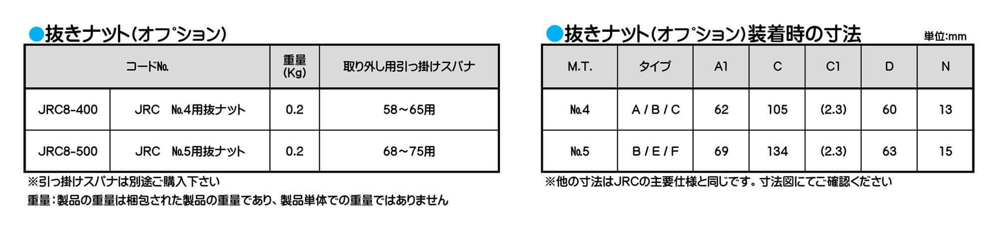
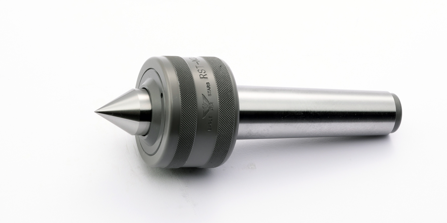
■M.T.、No.4、M.T.、No.5それぞれに細物仕様を設定
■オプションにて抜きナット装着可能
ローリングセンター
■最高回転数 3000min-1
■テーパローラベアリング仕様で、スムーズな低トルク設計
■本体はコンパクトで使いやすい回転領域(500min-1〜3000min-1)
■シールを標準搭載
■M.T.、No.4、M.T.、No.5それぞれに細物仕様を設定
■オプションにて抜きナット装着可能
ローリングセンター
■最高回転数 3000min-1
■テーパローラベアリング仕様で、スムーズな低トルク設計
■本体はコンパクトで使いやすい回転領域(500min-1〜3000min-1)
■シールを標準搭載
■M.T.、No.4、M.T.、No.5それぞれに細物仕様を設定
■オプションにて抜きナット装着可能
ローリングセンター

■最高回転数 3000min-1
■テーパローラベアリング仕様で、スムーズな低トルク設計
■本体はコンパクトで使いやすい回転領域(500min-1〜3000min-1)
■シールを標準搭載
■M.T.、No.4、M.T.、No.5それぞれに細物仕様を設定
■オプションにて抜きナット装着可能
ローリングセンター
■最高回転数 3000min-1
■テーパローラベアリング仕様で、スムーズな低トルク設計
■本体はコンパクトで使いやすい回転領域(500min-1〜3000min-1)
■シールを標準搭載
■M.T.、No.4、M.T.、No.5それぞれに細物仕様を設定
■オプションにて抜きナット装着可能
ローリングセンター
ローリングセンター
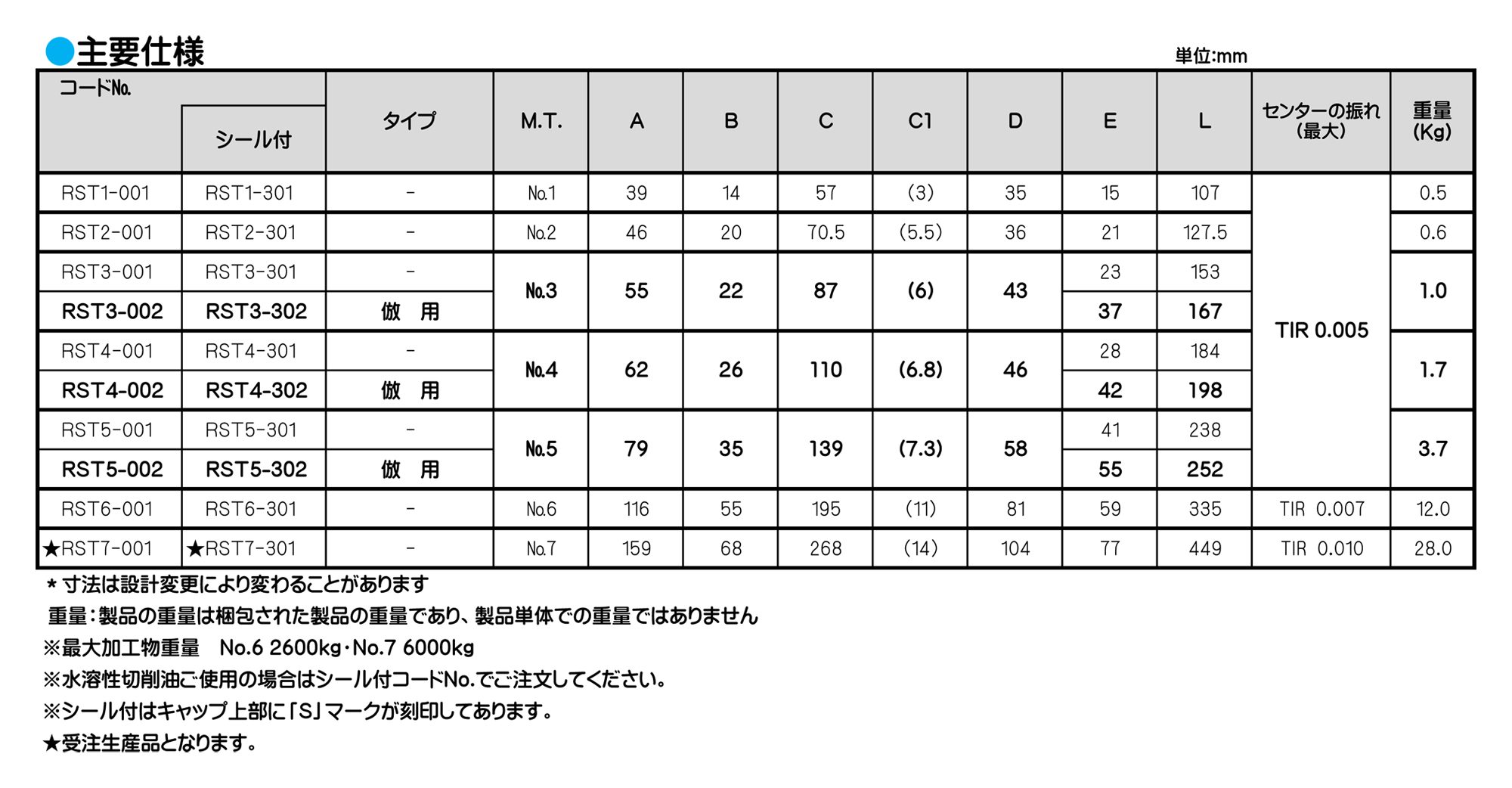
ローリングセンター
■重切削、一般切削最適品、最高回転数(No.3~No.5) 2500min-1
■本製品の内部にはM.T No.1、No.2はボールベアリング2ケ、スラストベアリング1ケ。
M.TNo.3~No.7はテーパローラベアリング、スラストベアリング、ボールベアリング各1ケの3種類を使用しています。
ローリングセンター
■重切削、一般切削最適品、最高回転数(No.3〜No.5) 2500min-1
■本製品の内部にはM.T No.1、No.2はボールベアリング2ケ、スラストベアリング1ケ。M.TNo.3〜No.7はテーパローラベアリング、スラストベアリング、ボールベアリング各1ケの3種類を使用しています。
ローリングセンター
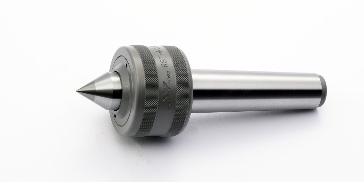
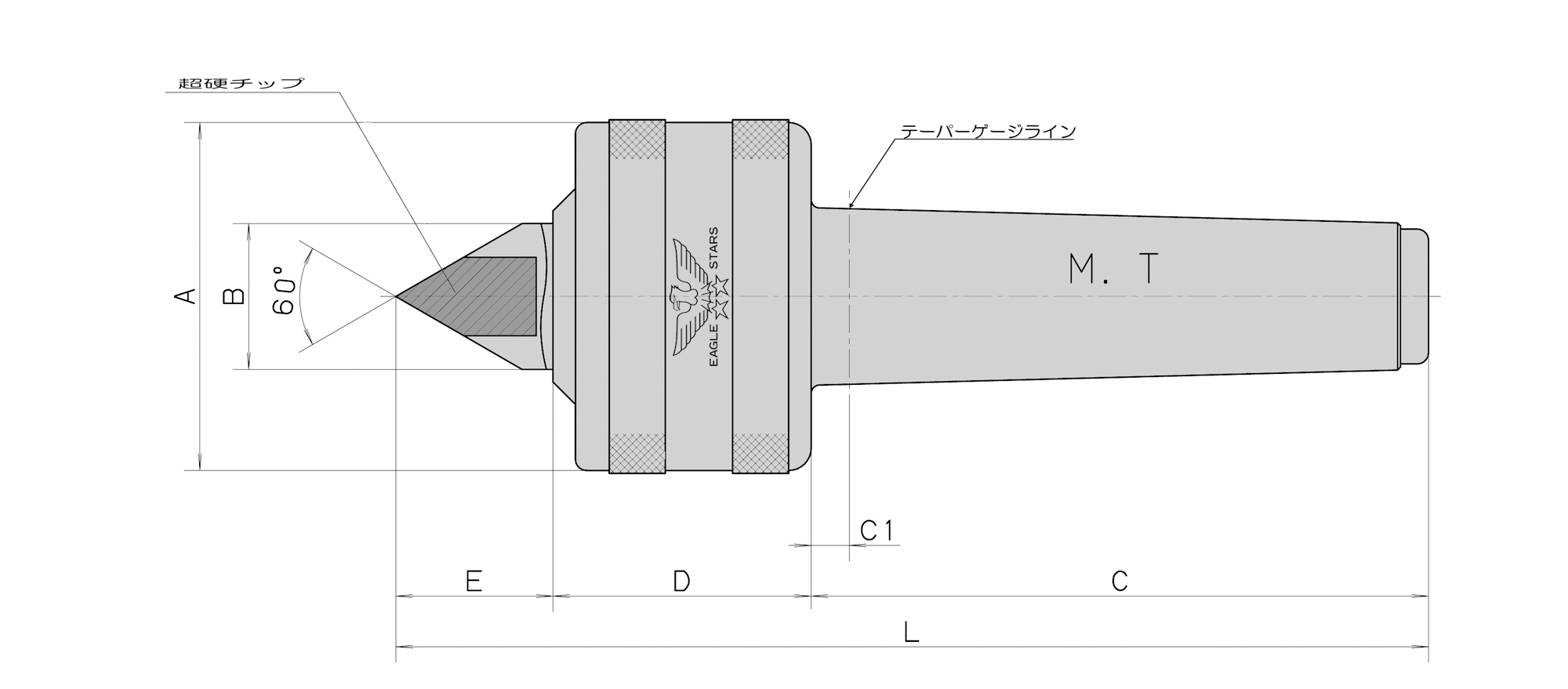
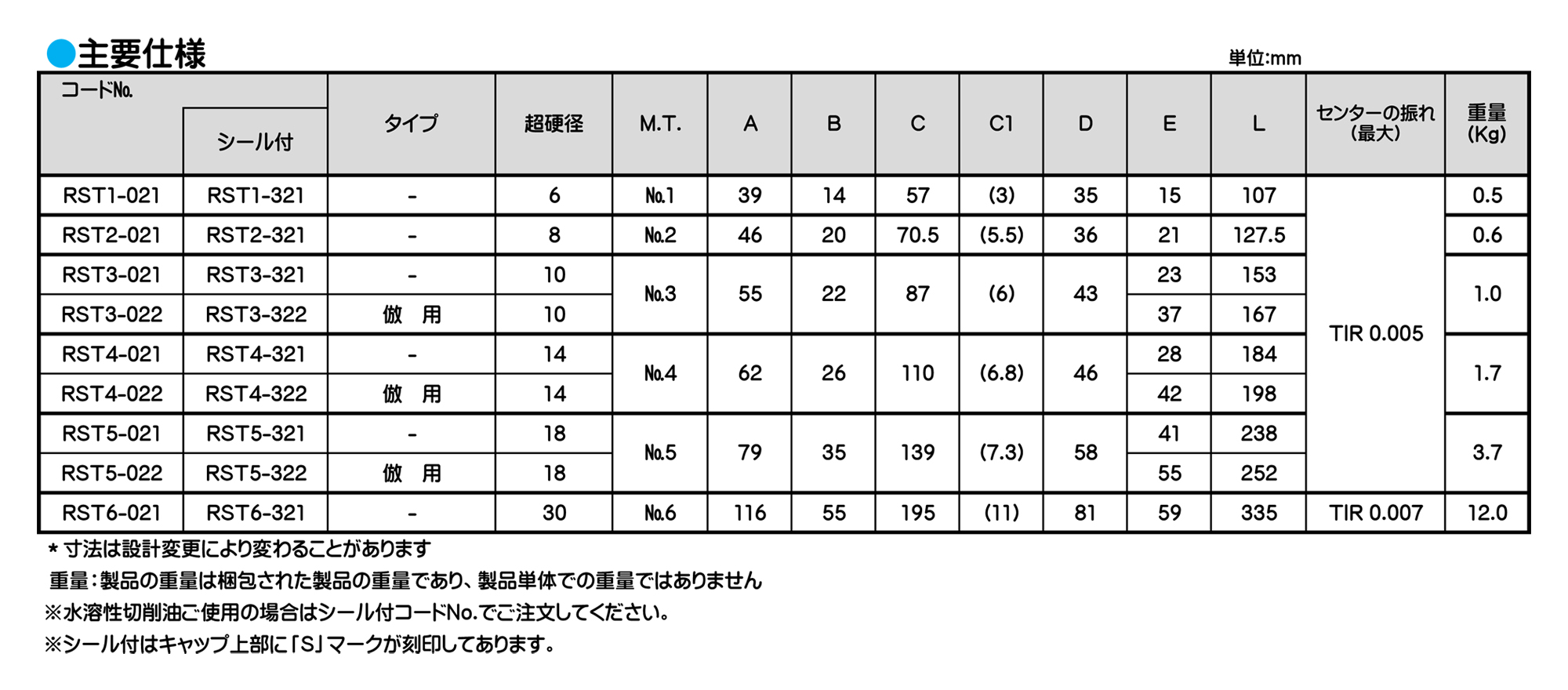
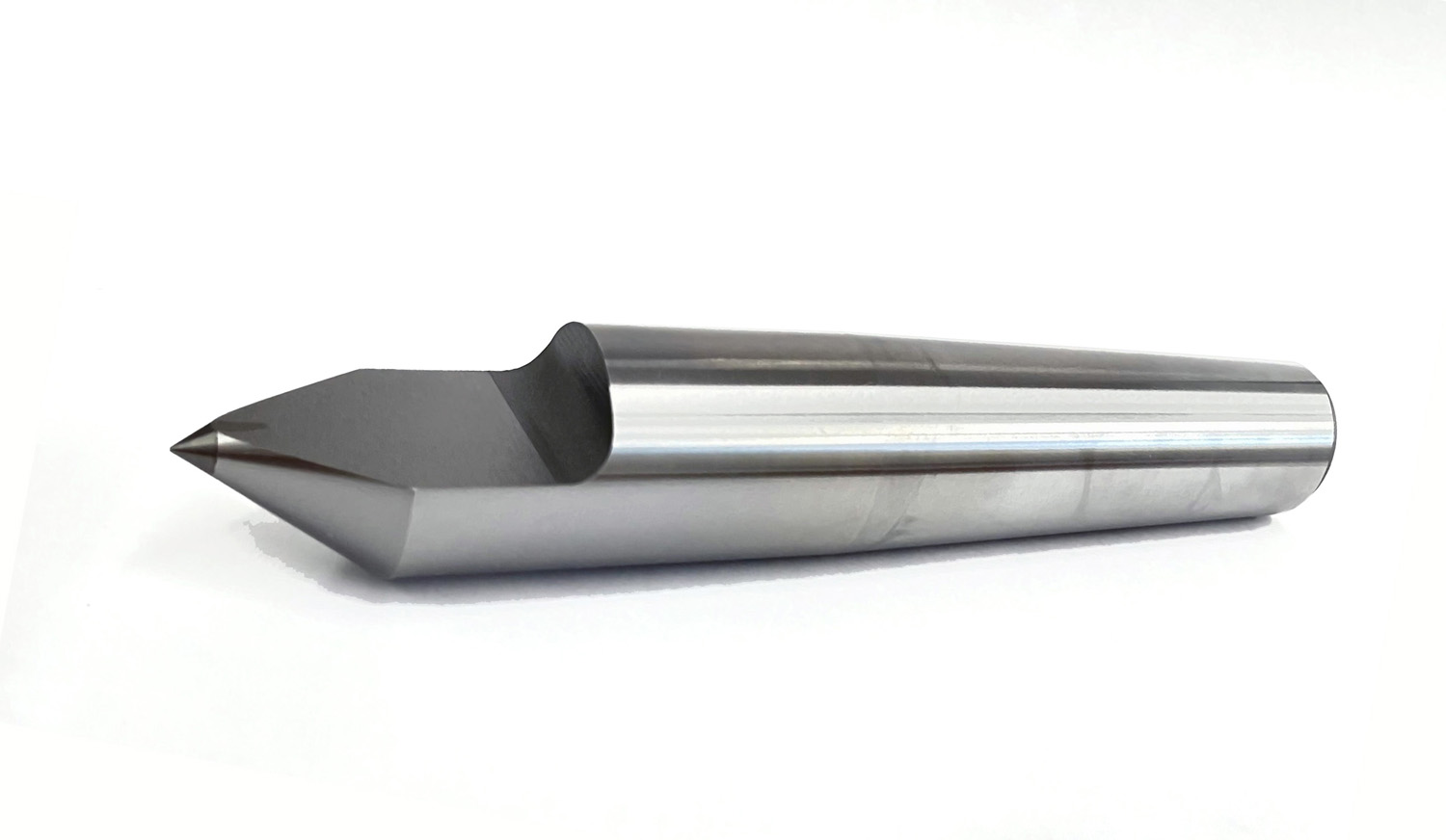
■外観、形状、構造はRST型と同じでありますが、センターの先端部に超硬合金チップがロー付けされています。
■先端部に超硬合金チップが付いているため耐摩耗、耐摩擦性に優れています。ご使用について
■超硬合金チップは衝撃に対して弱いため加工物を打ち当てないようご注意してください。
ローリングセンター
ローリングセンター
■標準型より更に重量物に耐えるよう使用ベアリングを大きく本体部外径、センター軸径が太く製作されています。
■受注製作品 φ80-1/10・φ80-1/20(メトリック)・φ100-1/20(メトリック)も製作できます。
ローリングセンター
■最高回転数(min-1)No.3=3500/No.4=3000/No.5=2500
■切削中に発生する加工熱による工作物の伸びをセンターに内蔵されている皿バネにより吸収するため、工作物のひずみが無く仕上げ精度がよくなります。
■工作物の伸びにより発生するスラスト荷重もスライド機構により吸収し、直接ベアリングに荷重がかからないよう設計されております。
ご使用について
■MAXストローク(e寸法、キャップよりデッドラインまでの距離)組付け時のスラスト初圧は、No.3=50kgf、No.4=100kgf、No.5=200kgf)に設定してありますので、加工物をセットされましたら、0.5mm~1mm程度押し込んでご使用してください。なお、上記e寸法まで押し込んで使用されますと、本機種の性能が発揮されませんのでご注意ください。
※初圧組立時より1mm押し込んだ場合のバネ圧はNo.3で+25kgf、No.4で+50kgf、No.5で+100kgfとなります。
ローリングセンター
ローリングセンター
■小物切削最適品、タイプAは細物タイプでネジ切り、端面加工に最適です。
■本製品にはニードルベアリング2ケ、スラストベアリングの3点のベアリングを使用し、本体径を小さく設計されております。
■Vシールを採用しており、切削油をご使用の場合最適です。
ご使用について
■構造上、センター軸に対して無負荷の場合センター軸が0.5mm程度前後します。使用時には推力をかけてご使用ください。
■ご使用時には必ずドレン孔(水抜き)を下向きに取り付けてご使用ください。
ローリングセンター
■小物切削最適品、タイプAは細物タイプでネジ切り、端面加工に最適です。
■本製品にはニードルベアリング2ケ、スラストベアリングの3点のベアリングを使用し、本体径を小さく設計されております。
■Vシールを採用しており、切削油をご使用の場合最適です。
ご使用について
■構造上、センター軸に対して無負荷の場合センター軸が0.5mm程度前後します。使用時には推力をかけてご使用ください。
■ご使用時には必ずドレン孔(水抜き)を下向きに取り付けてご使用ください。
ローリングセンター

■小物切削最適品、タイプAは細物タイプでネジ切り、端面加工に最適です。
■本製品にはニードルベアリング2ケ、スラストベアリングの3点のベアリングを使用し、本体径を小さく設計されております。
■Vシールを採用しており、切削油をご使用の場合最適です。
ご使用について
■構造上、センター軸に対して無負荷の場合センター軸が0.5mm程度前後します。使用時には推力をかけてご使用ください。
■ご使用時には必ずドレン孔(水抜き)を下向きに取り付けてご使用ください。
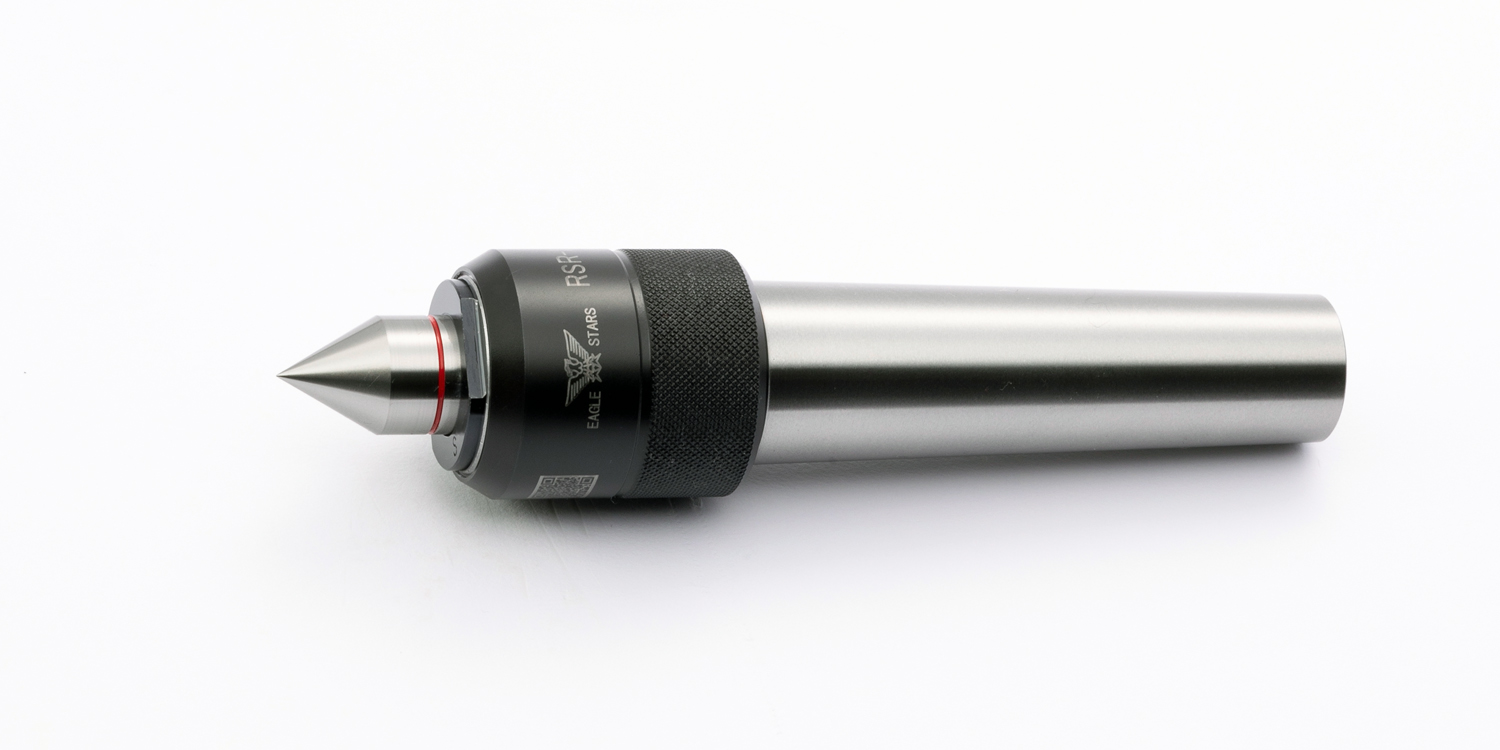
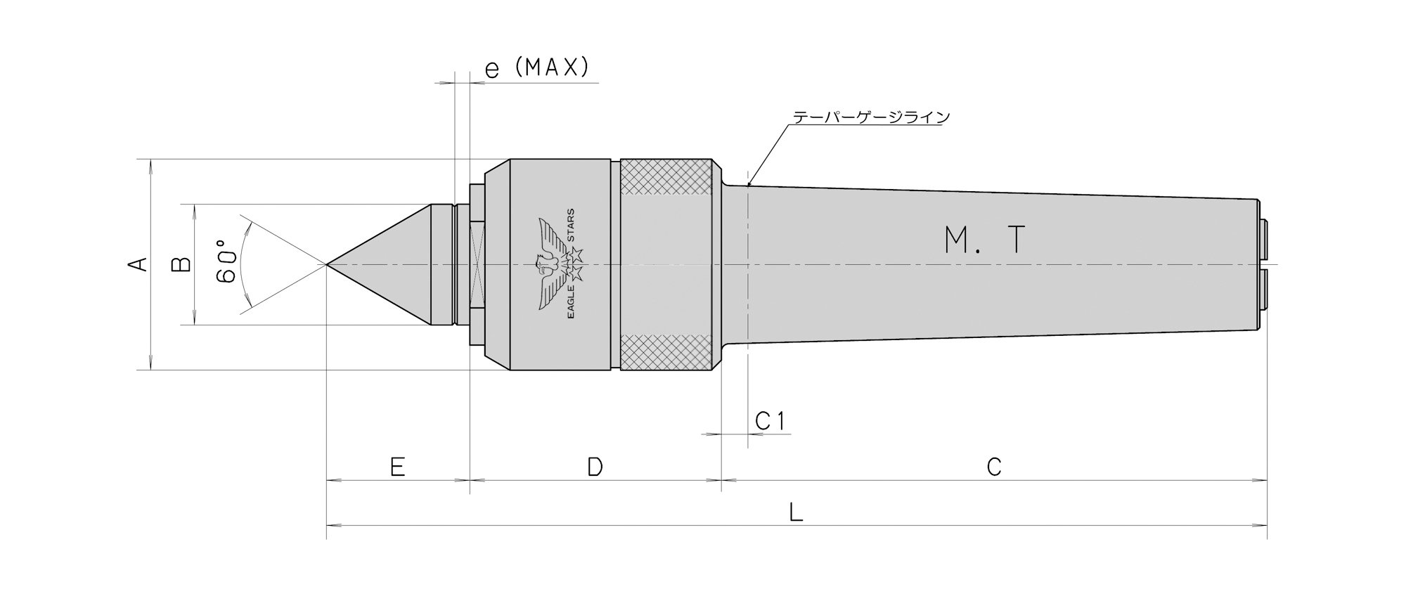
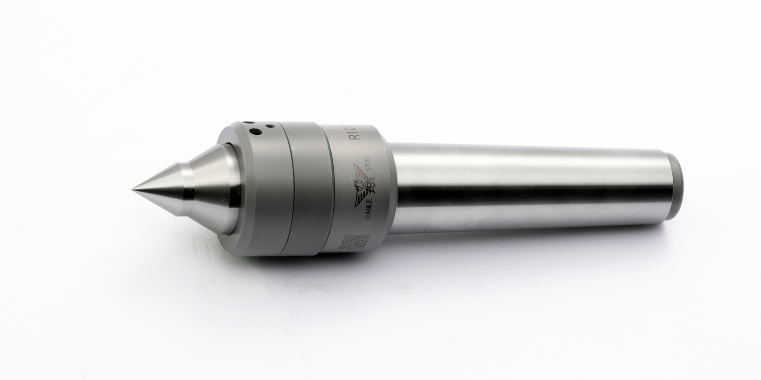
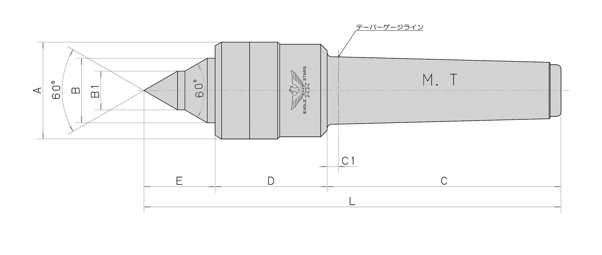
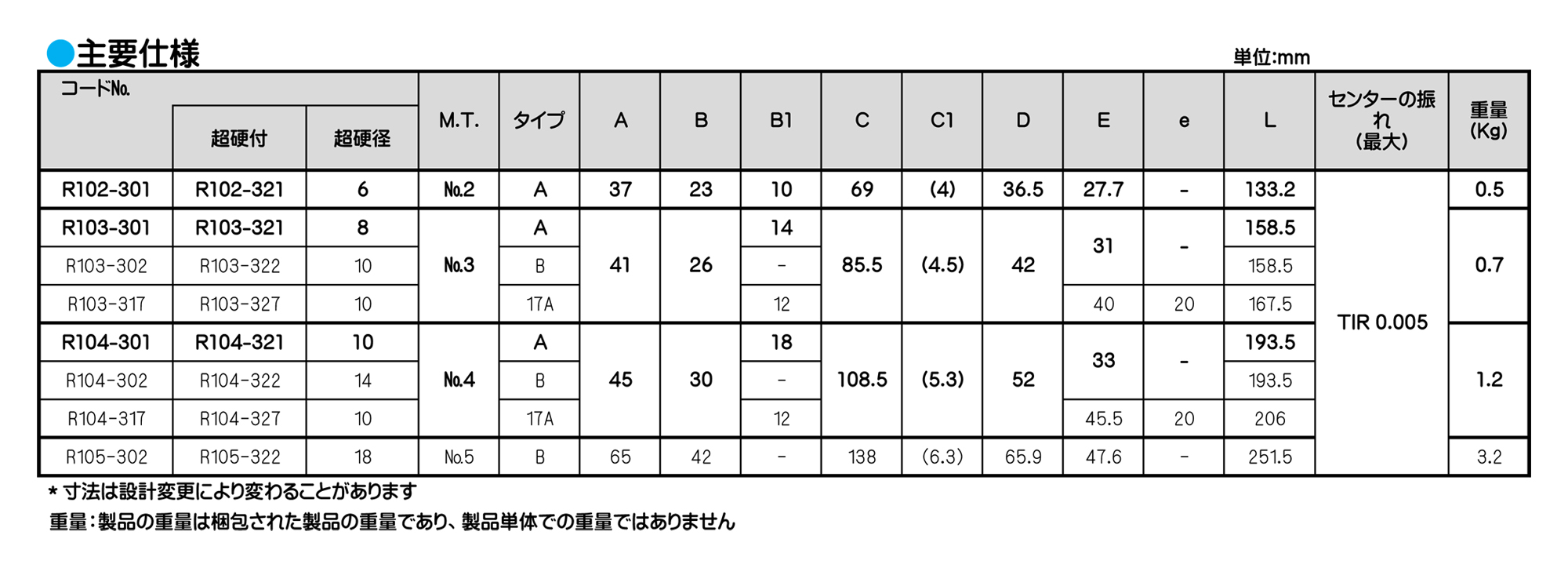
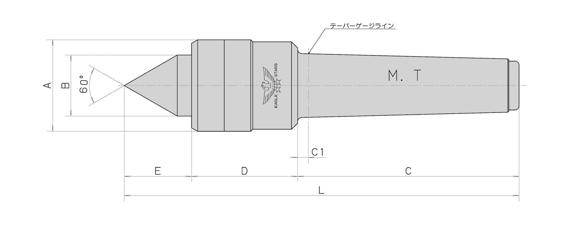
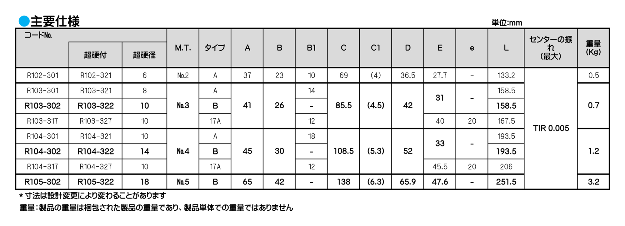
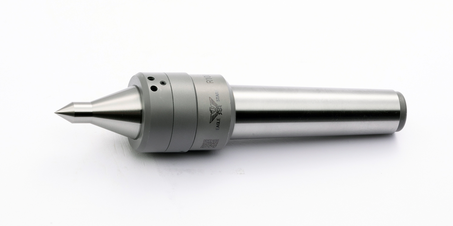
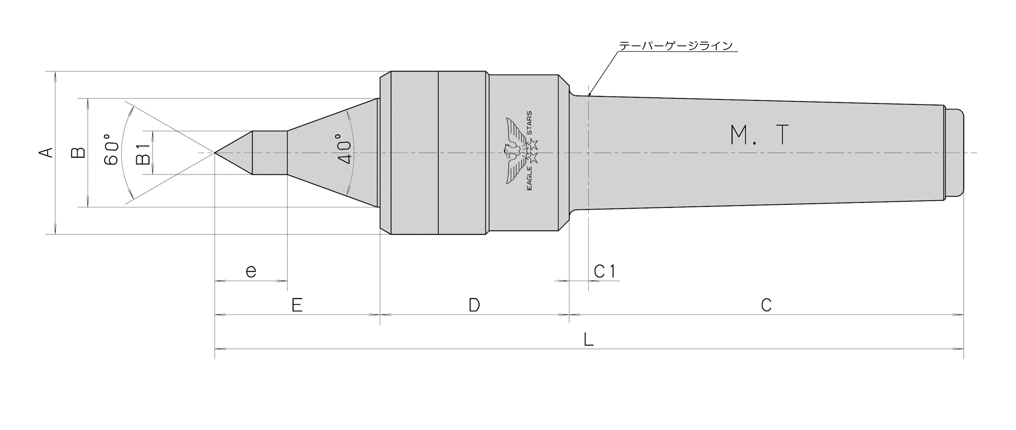
ローリングセンター
ローリングセンター
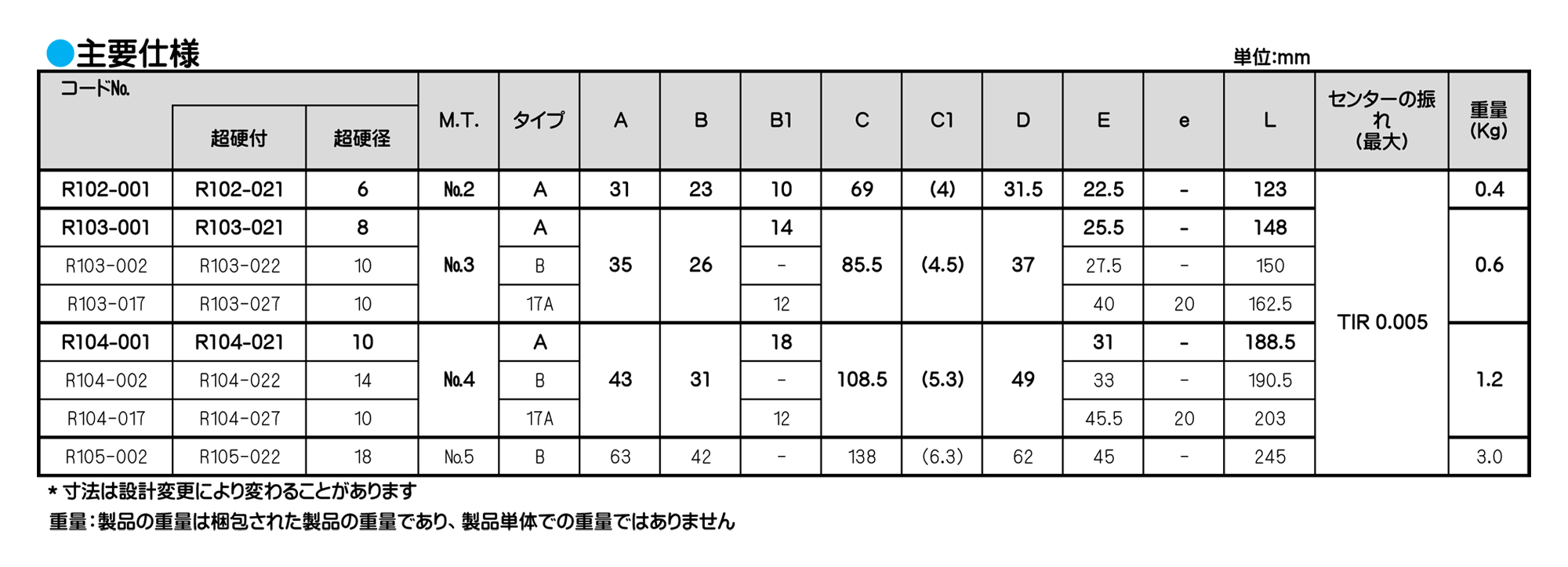
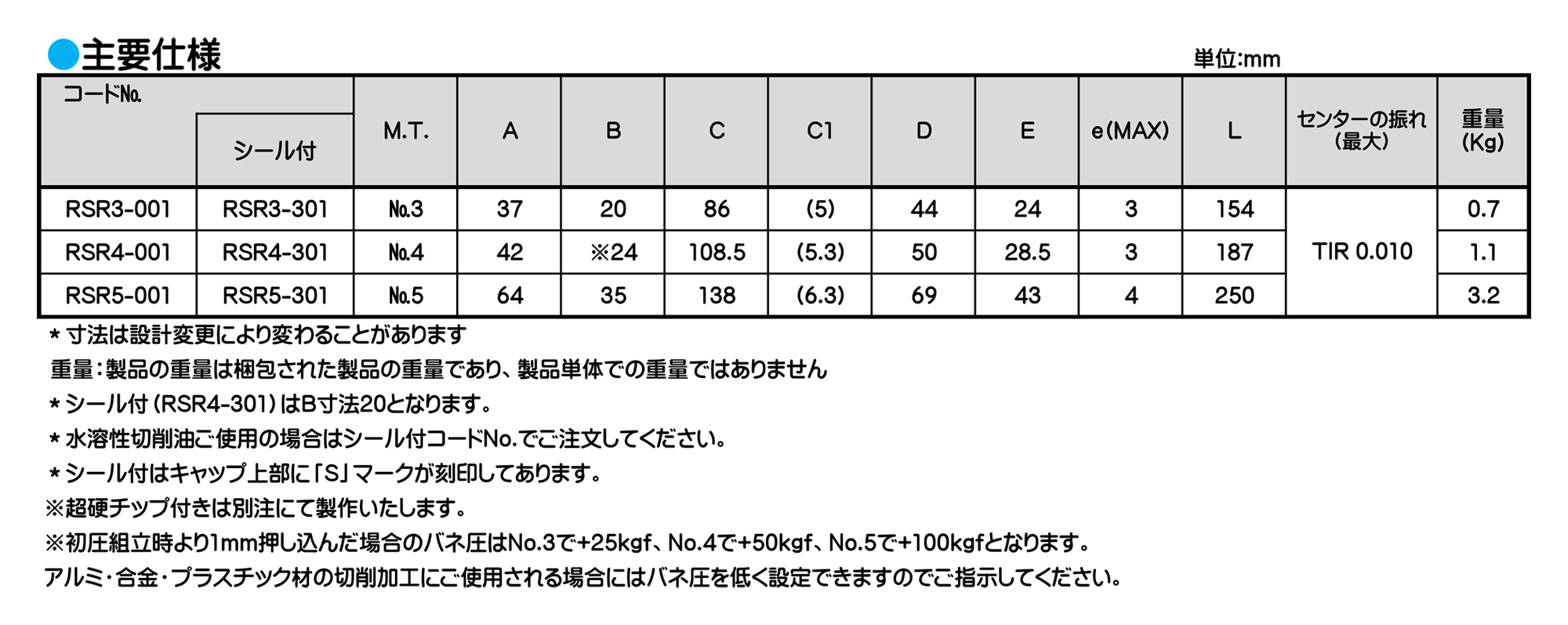
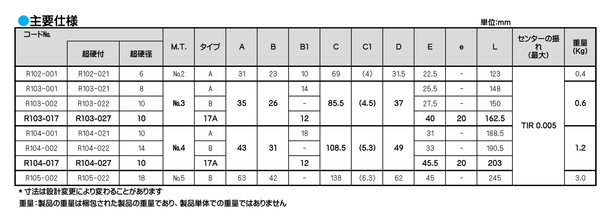
■最高回転数(min-1)102=3500 103=3000 104=3000 105=2500
■小物切削最適品、タイプAは細物タイプでネジ切り、端面加工に最適です。
■本製品の内部にはニードルベアリング2ケ、スラストベアリングの3点のベアリングを使用し、本体径を小さく設計されております。
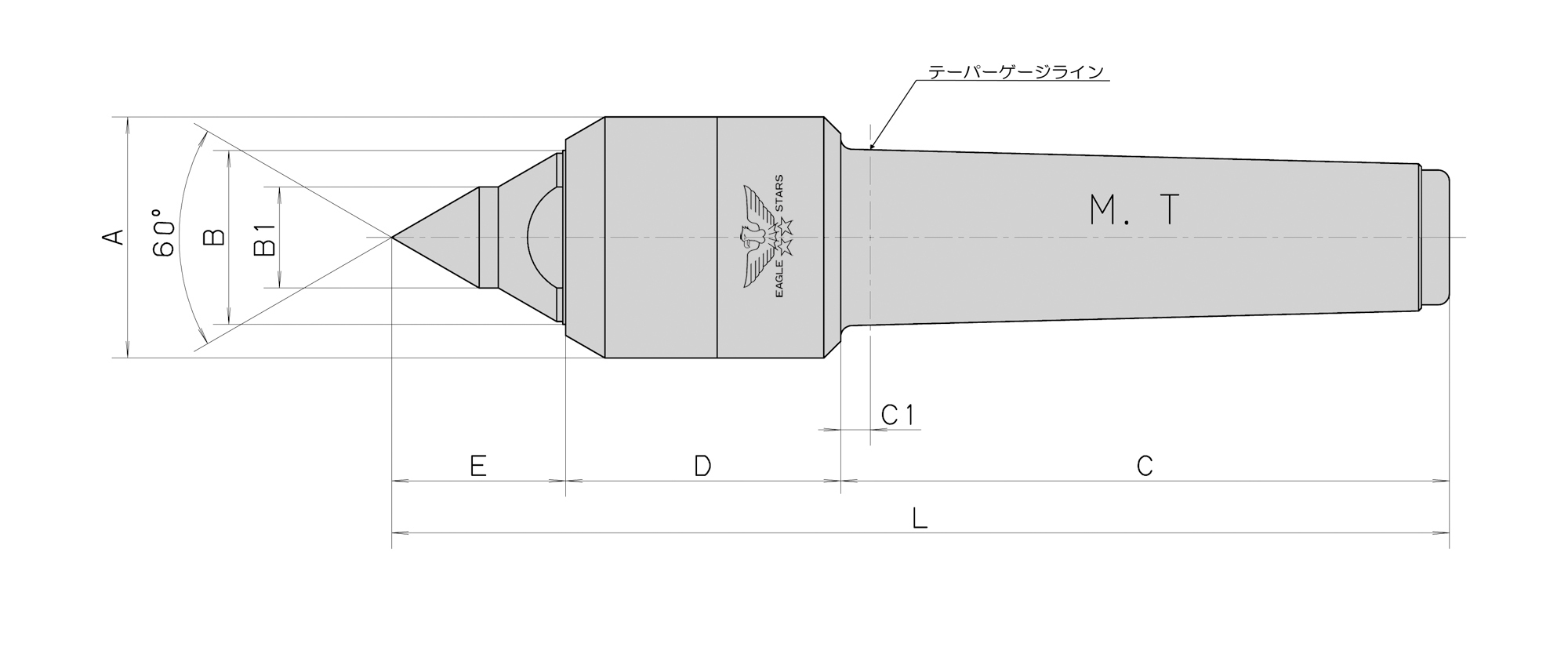
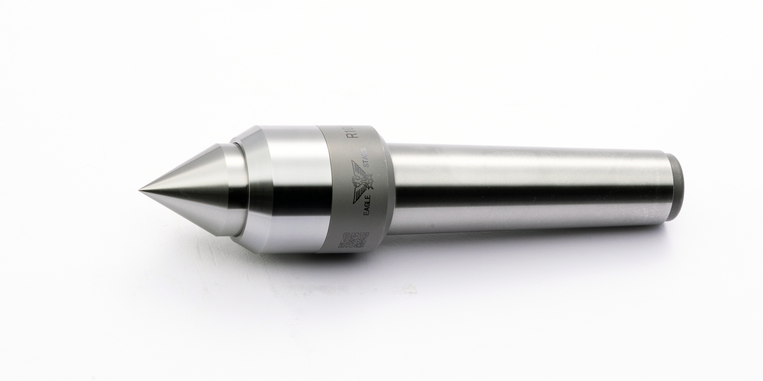
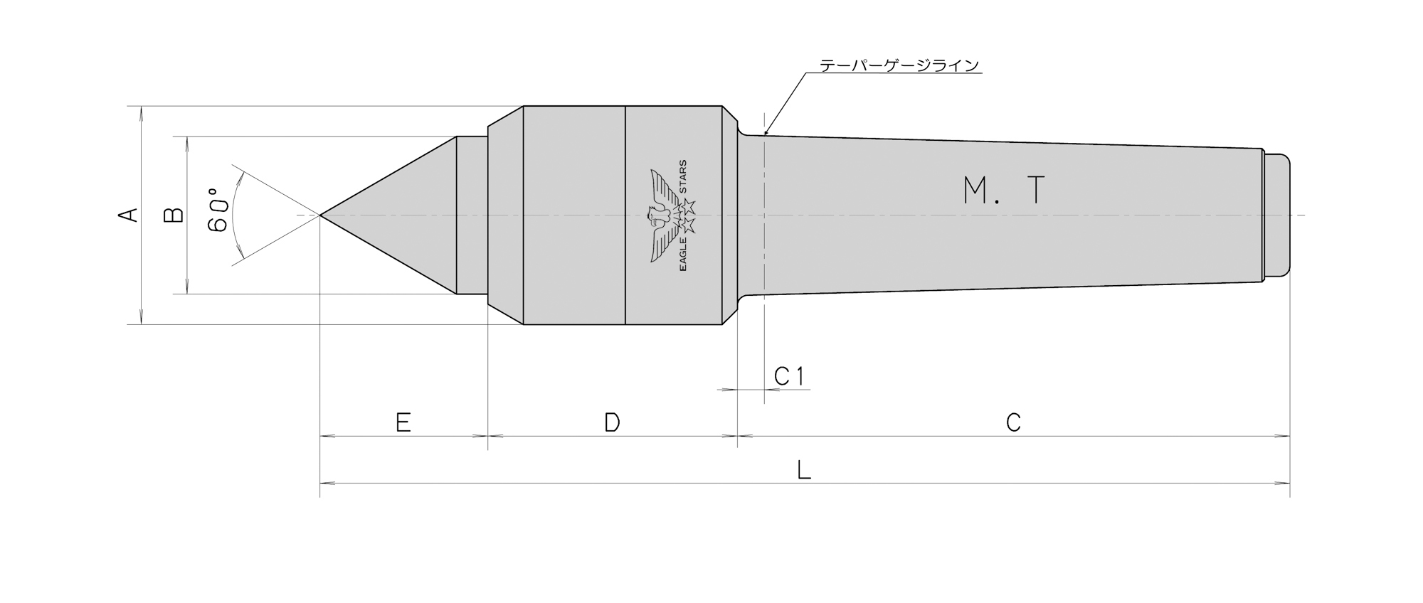
■本体頭部はセンターの先端から60°の角度内に納めてあるためバイトの進入に対して干渉がありません。
ご使用について
■構造上、センター軸に対して無負荷の場合センター軸が0.5mm程度前後します。使用時には推力をかけてご使用ください。
■切削水等をご使用の場合は、シール付をお選びください。
ローリングセンター

■最高回転数(min-1)102=3500 103=3000 104=3000 105=2500
■小物切削最適品、タイプAは細物タイプでネジ切り、端面加工に最適です。
■本製品の内部にはニードルベアリング2ケ、スラストベアリングの3点のベアリングを使用し、本体径を小さく設計されております。
■本体頭部はセンターの先端から60°の角度内に納めてあるためバイトの進入に対して干渉がありません。
ご使用について
■構造上、センター軸に対して無負荷の場合センター軸が0.5mm程度前後します。使用時には推力をかけてご使用ください。
■切削水等をご使用の場合は、シール付をお選びください。
ローリングセンター

特殊品 〈3点保持回転センター〉
■研削盤・測定機でのご使用をお勧めします。
■中空ワークやパイプ形状のワークは熱処理後の変形により図Aのように楕円形状になりやすい。そのためセンター穴を円錐60°で保持しようとした場合、2点で保持することになります。
■3点で保持する事でワークの中心を保持する事が可能です。
◆上記写真の製品は先端円錐部分(60°)に3ヶ所超硬チップをロー付してあります。
◆図Bのように先端円錐部分を3ヶ所カットした形状も製作可能です。
※センター穴が小径の場合に対応
ローリングセンター
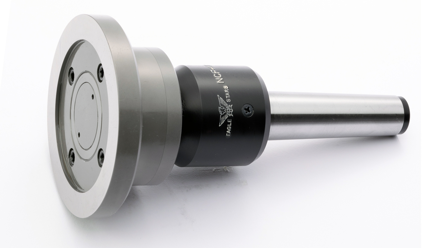
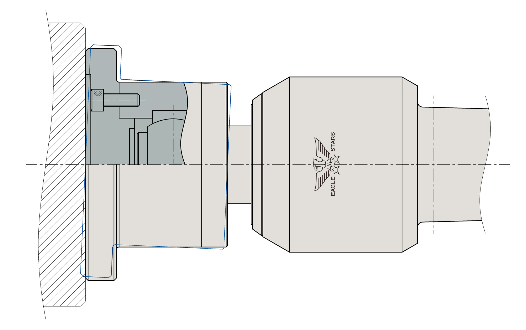
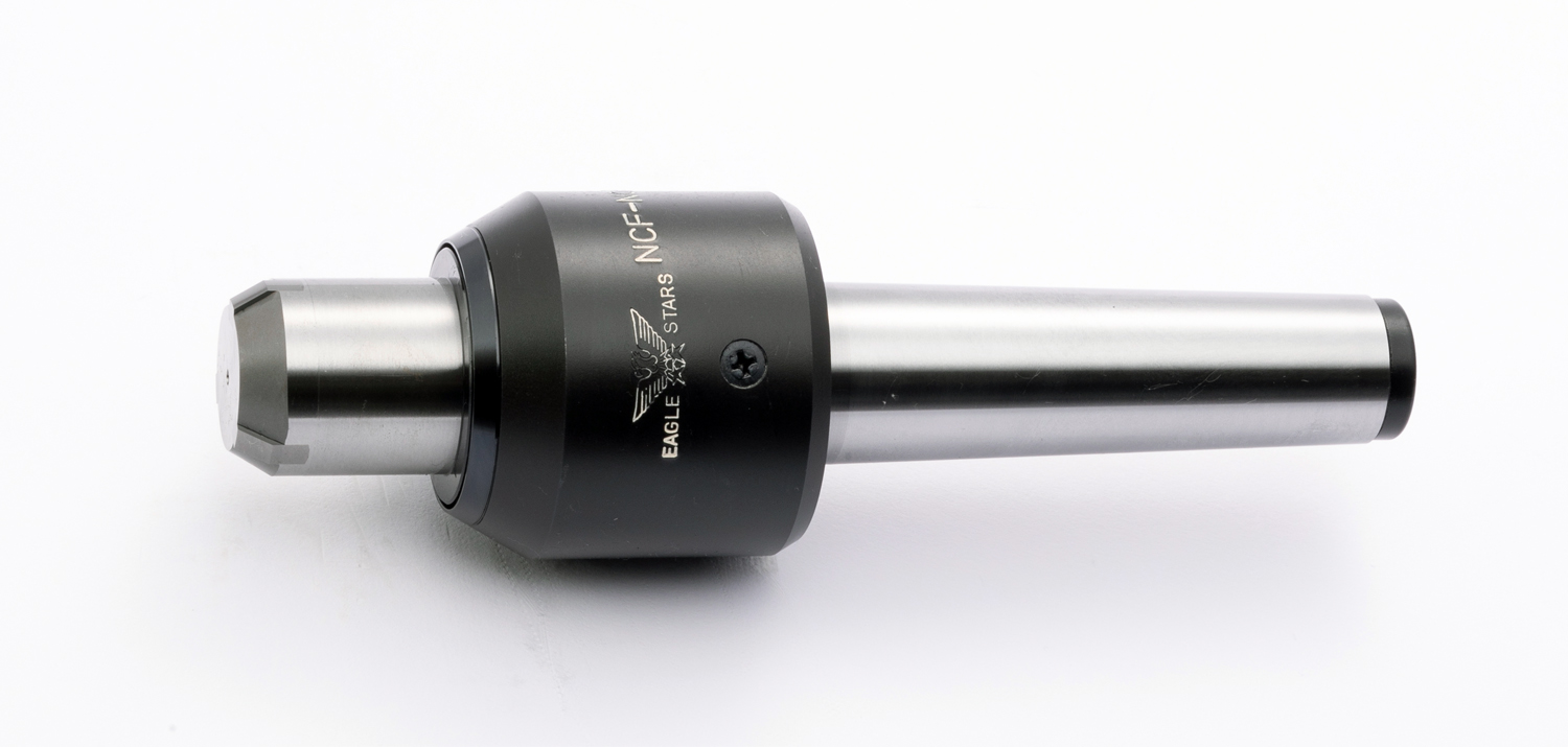
特殊品〈先端フローティング式〉
■ワークと接するフランジ部分がフローティングします。
■フローティング方法は球面滑り軸受(図)を使用したものと球面座式を使用したものがあります。
■先端フランジ部分はOリングのゴムにより復元いたします。
■ワークと接するフランジ部分は、寸法によって交換が可能となります。
◆フランジ形状のワーク(プレス品・ギヤなど)外径部分を加工する際にアーバーコレットなどにより内径部を把握します。この様なケースでワーク保持力が弱く、加工条件を上げられない場合にお勧め致します。
◆センター穴が無いワークなど、面圧などで保持したい場合にご使用頂けます。
ローリングセンター
特殊品〈端面加工用〉
■先端を矢じり形状にすることで加工物の端面より加工する事が可能です。
ローリングセンター
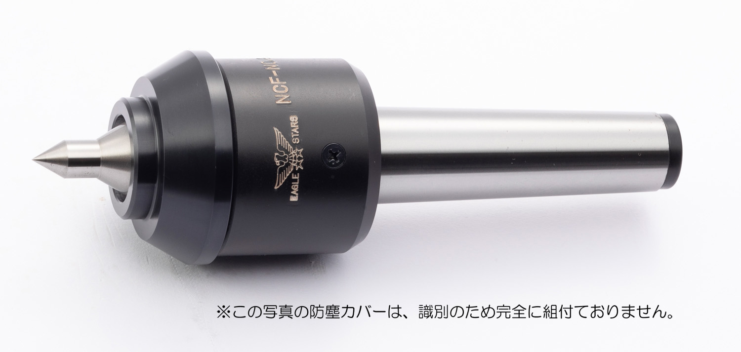
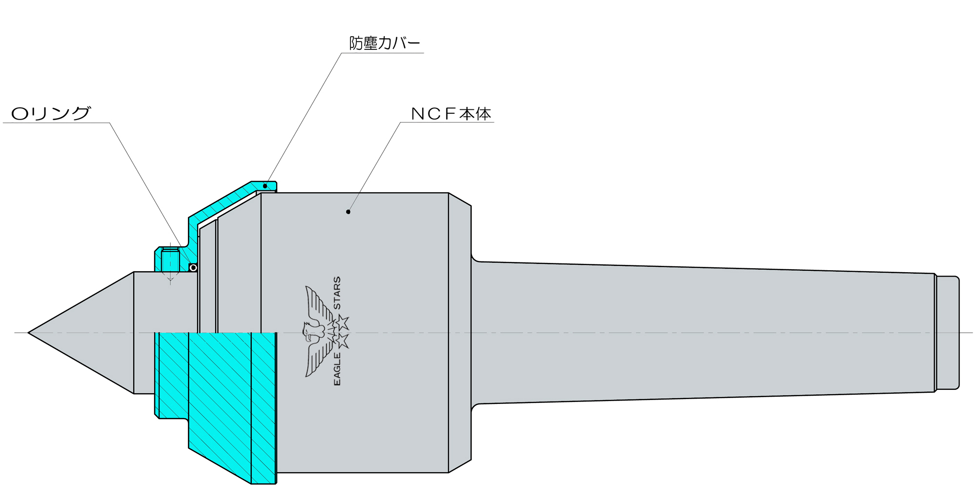
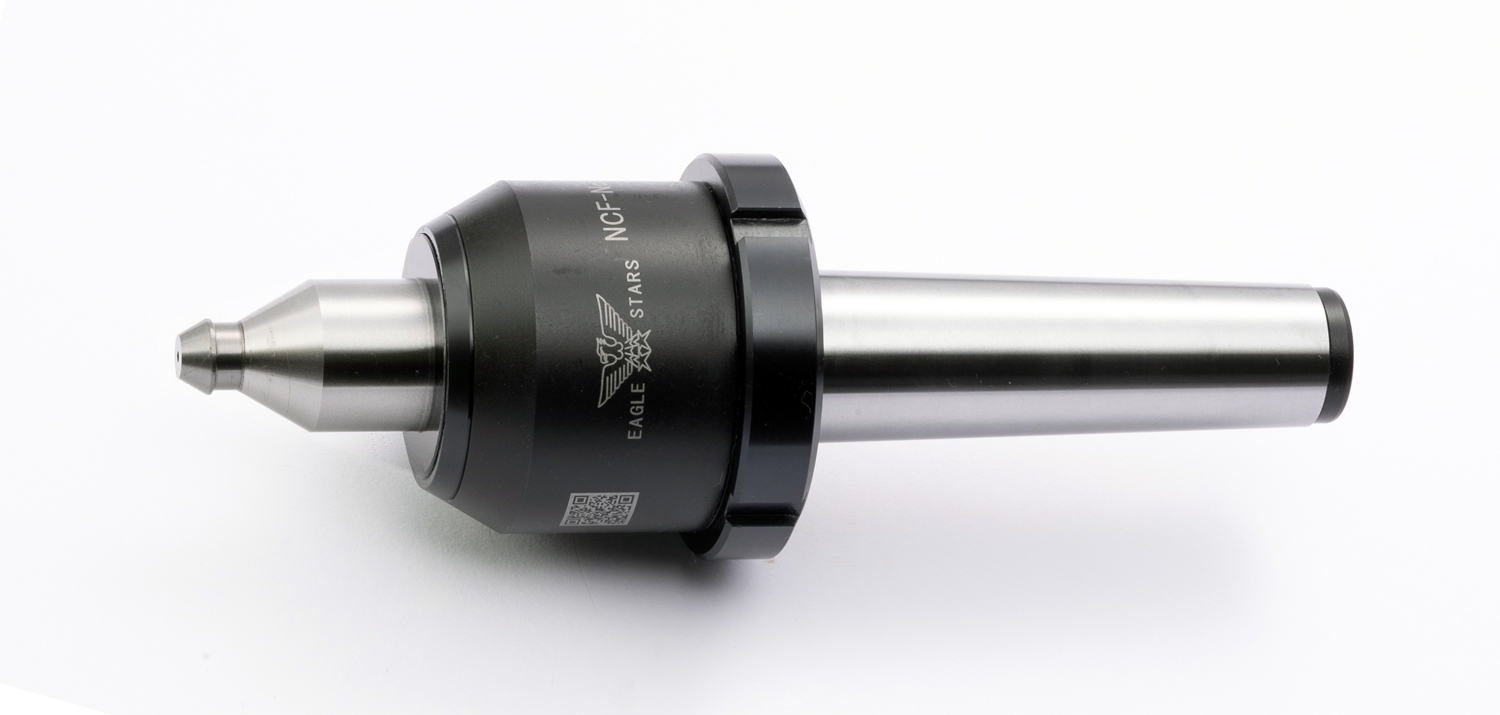
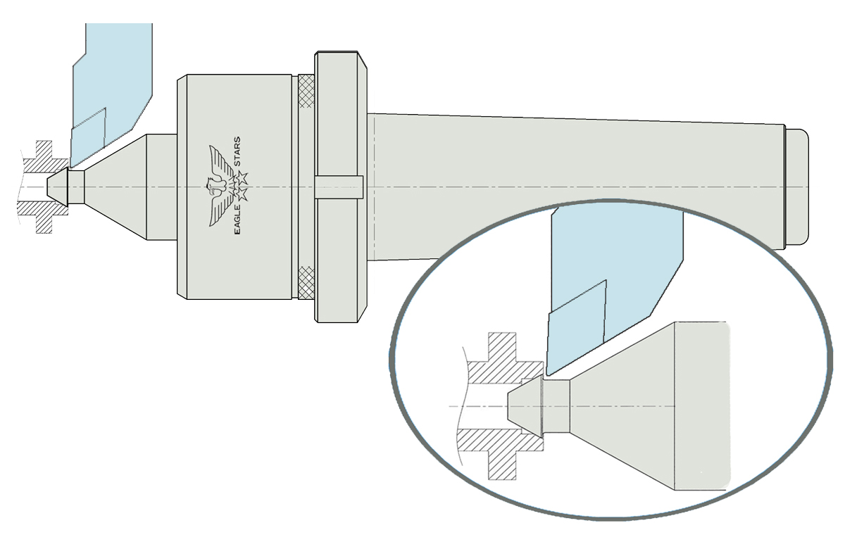
特殊品〈防塵カバー〉
■こんな時には、防塵カバー付きの回転センターがお勧めです。
シール部分に直接クーラントがかかり困っている。
研磨粉、クーラントの汚泥が侵入して困っている。
ラビリンスシール、Vシールではクーラントの侵入が防げない。
縦型旋盤の下側に装着したい。
◆防塵カバーは本体とセットでご注文ください。
ローリングセンター
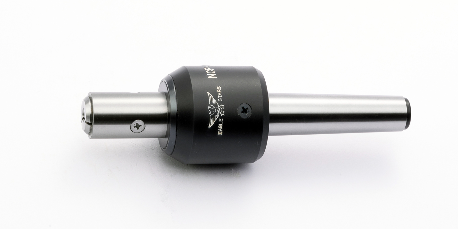
特殊品〈コレットチャック付〉
■センター軸にコレットチャックが組み込まれており加工物を押すと(推力)コレットチャックが締まり加工物を把握します。
■外径基準の加工物(モーターの軸、コピー、プリンター、ファックスのシャフト、ゴムロール等)の切削加工、研削加工。
■センター穴がない加工物。■固定式コレットチャックセンターも製作しています。
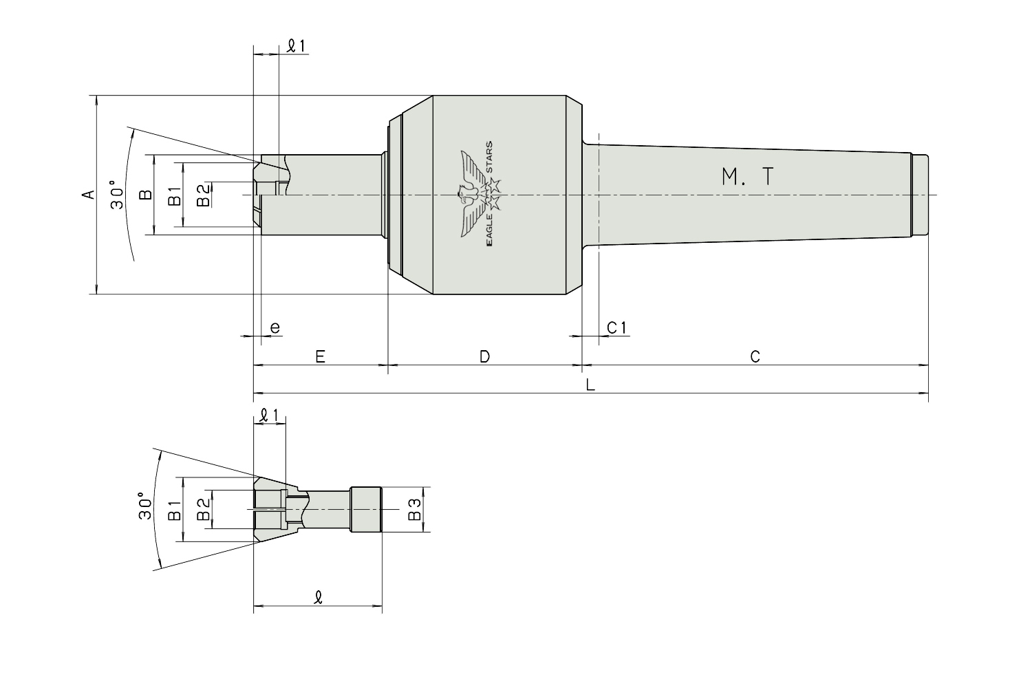
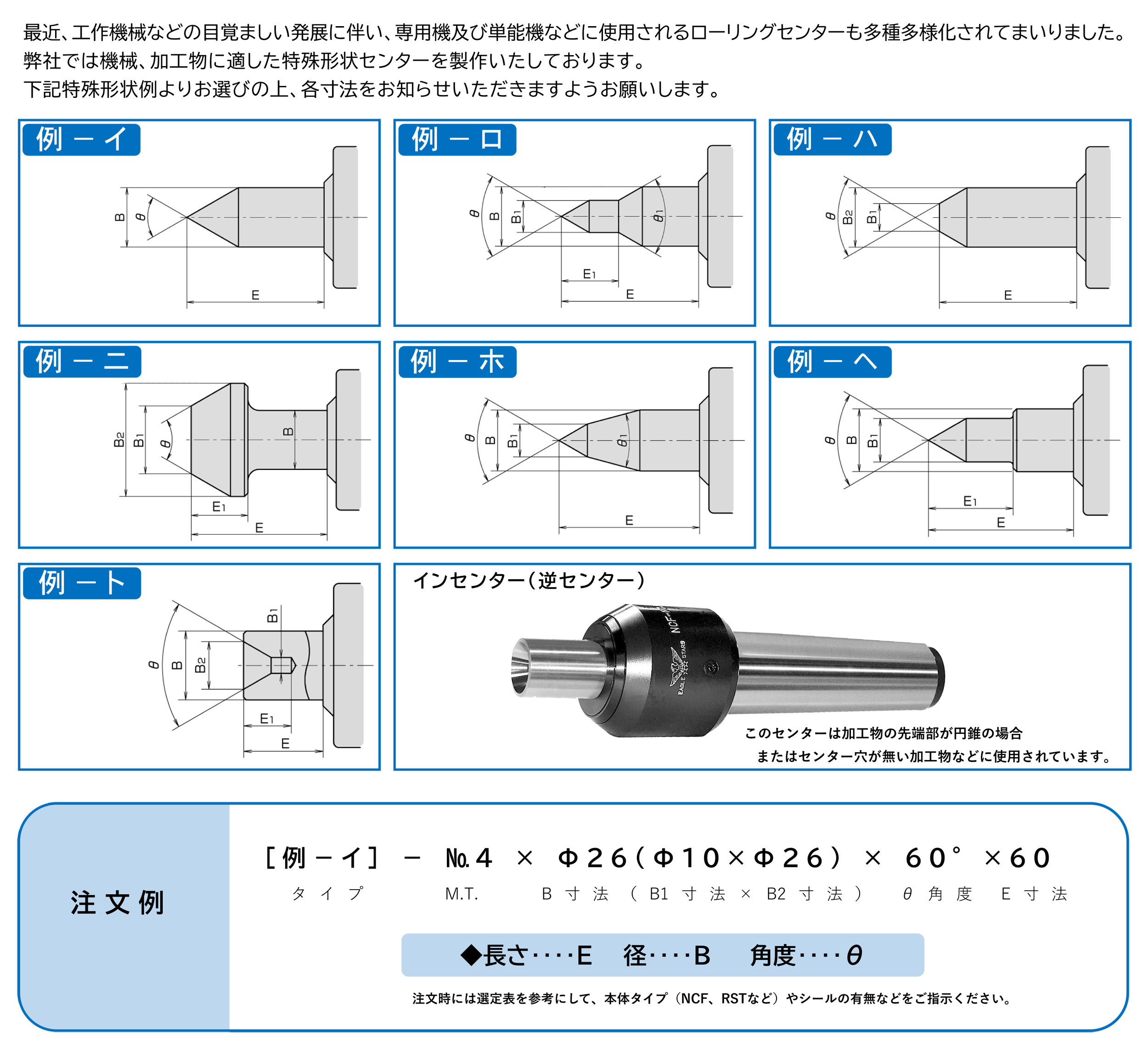
◆ご注文時にはコレットに必要な寸法(B2=把握する径、ℓ1=深さ)をお知らせください。納期、価格については別途お見積もりさせていただきます。
ローリングセンター
■注) B寸法(センター軸径)はベアリング本体などの関係がございますのでなるべく標準品ローリングセンターの中からお選びください。
■※納期、価格については別途お見積もりさせていただきます。
■最近、工作機械などの目覚ましい発展に伴い、専用機及び単能機などに使用されるローリングセンターも多種多様化されてまいりました。弊社では機械、加工物に適した特殊形状センターを製作いたしております。
上記特殊形状例よりお選びの上、各寸法をお知らせいただきますようお願いします。
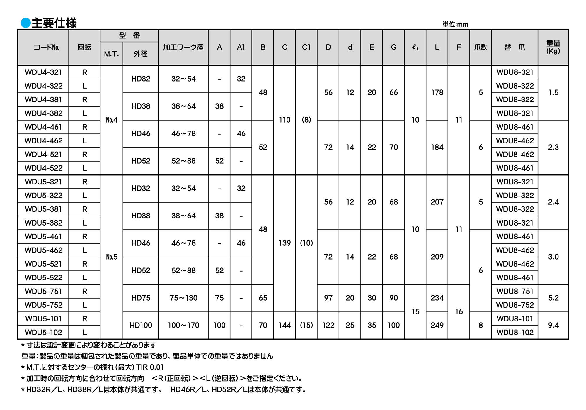
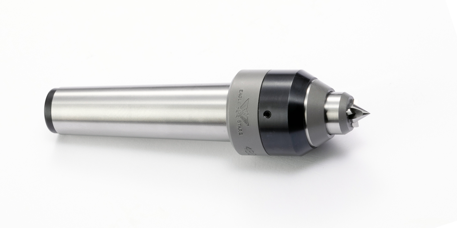
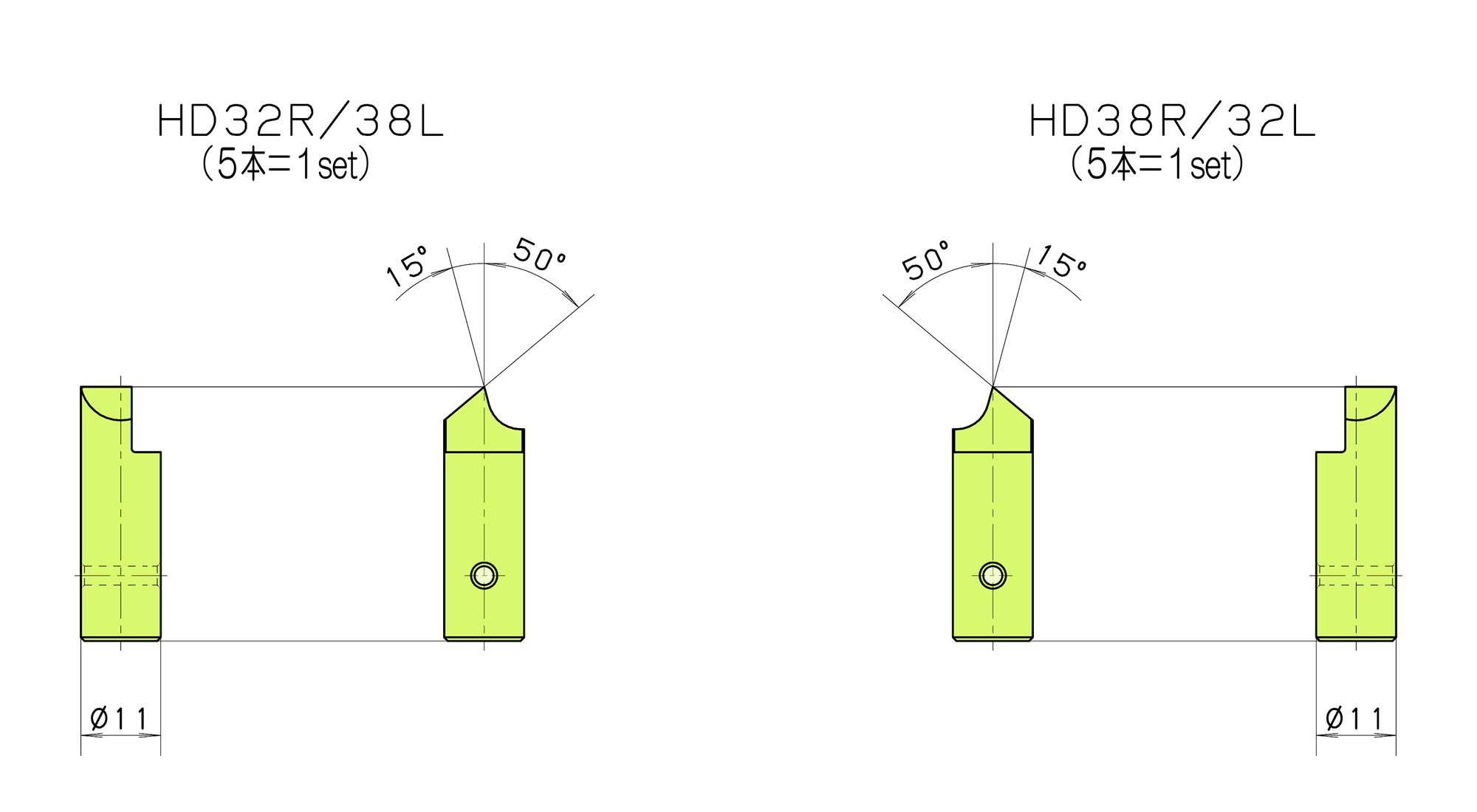
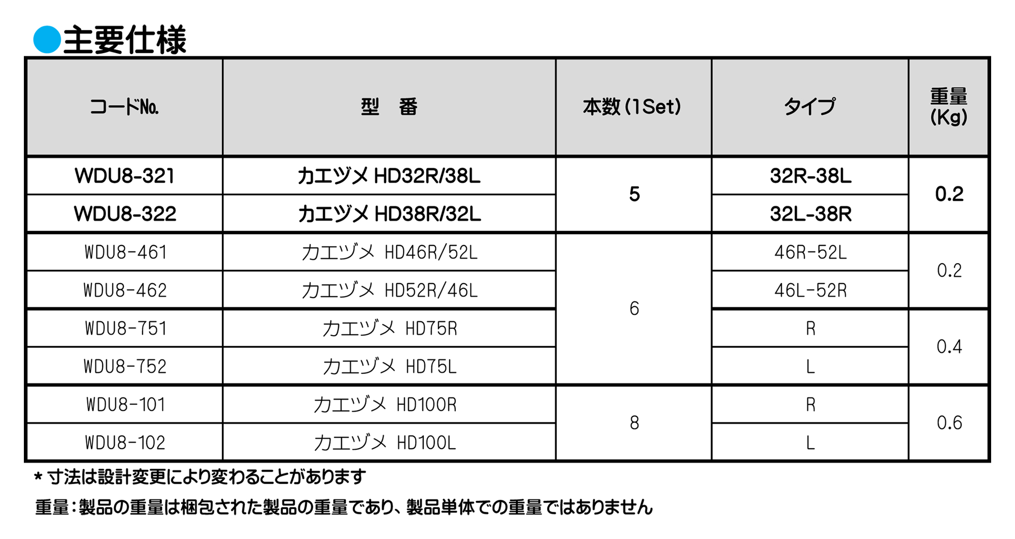
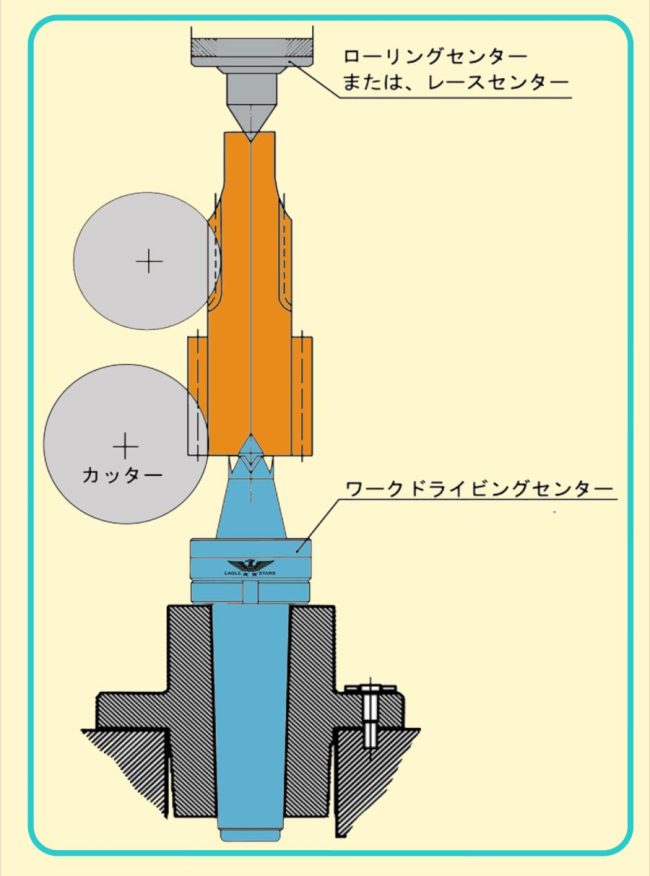
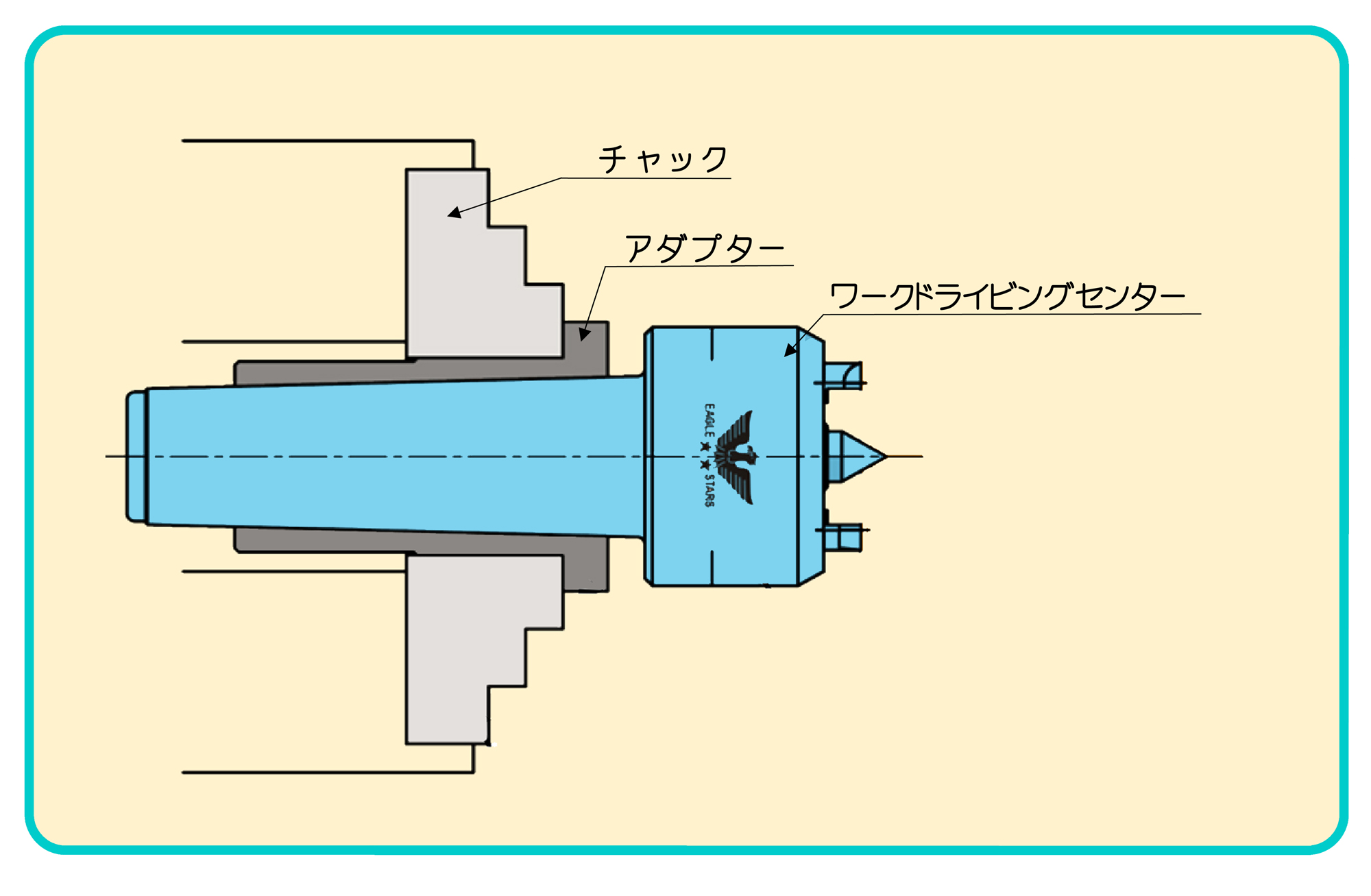
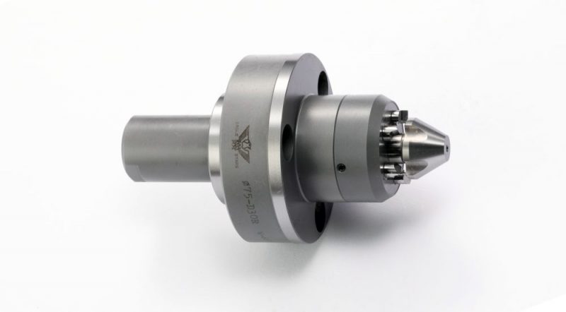
ワークドライビングセンター
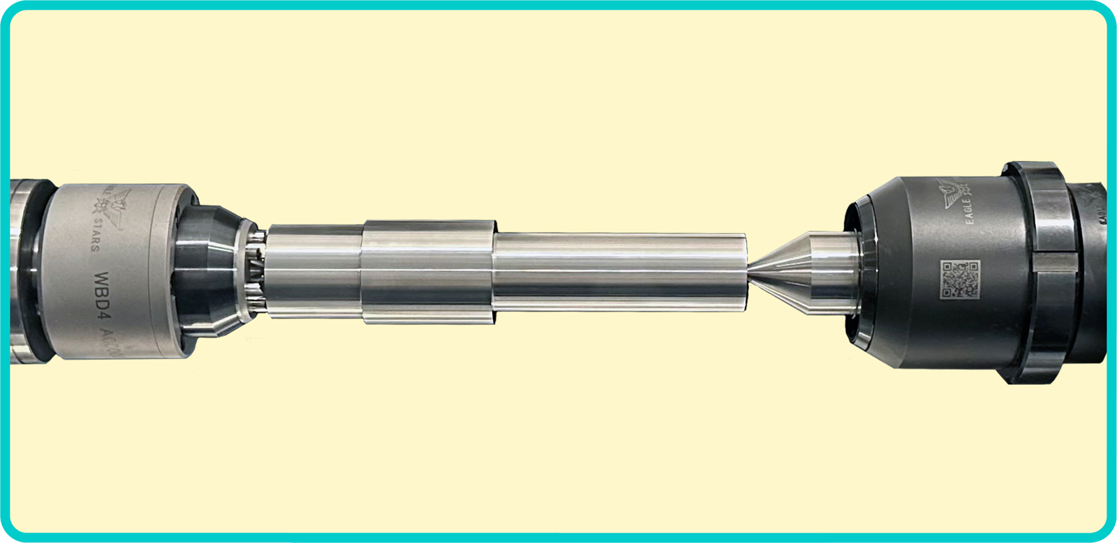
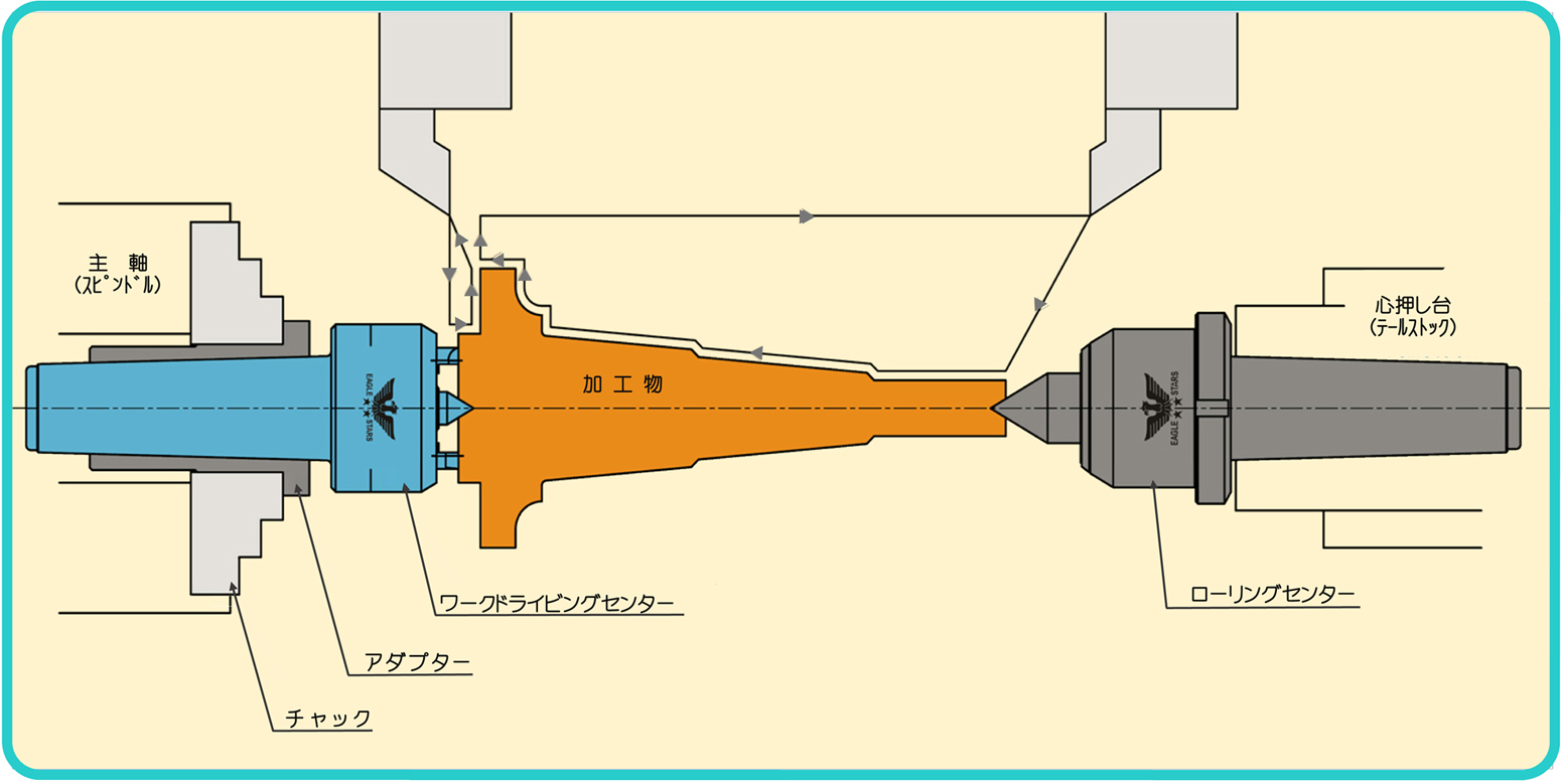
■本製品の使用により、両センター加工で加工物の端面に多少の傾斜がある場合にも、爪が鋭敏に作動して均等に把握し、加工物を保持します。
■加工物の端面を保持するためチャックの掴み代を必要とせず、加工物の端から端まで一度の切削加工で仕上げられます。これにより、反転して取付加工の必要がなく、材料の節約、ロスタイムの節約、精度の均一化を図ることができます。
■両センターにて加工する場合、レースドッグ(ケレー)を使用する必要がなく、作業能率を向上させます。
■機械に装着後、本製品の操作は不要です。
■ワークドライビングセンター用アダプターとの併用により、本製品を簡単にチャックに取り付ける事ができます。
■爪が消耗したり、破損した場合は交換用の替爪を用意いたしております。
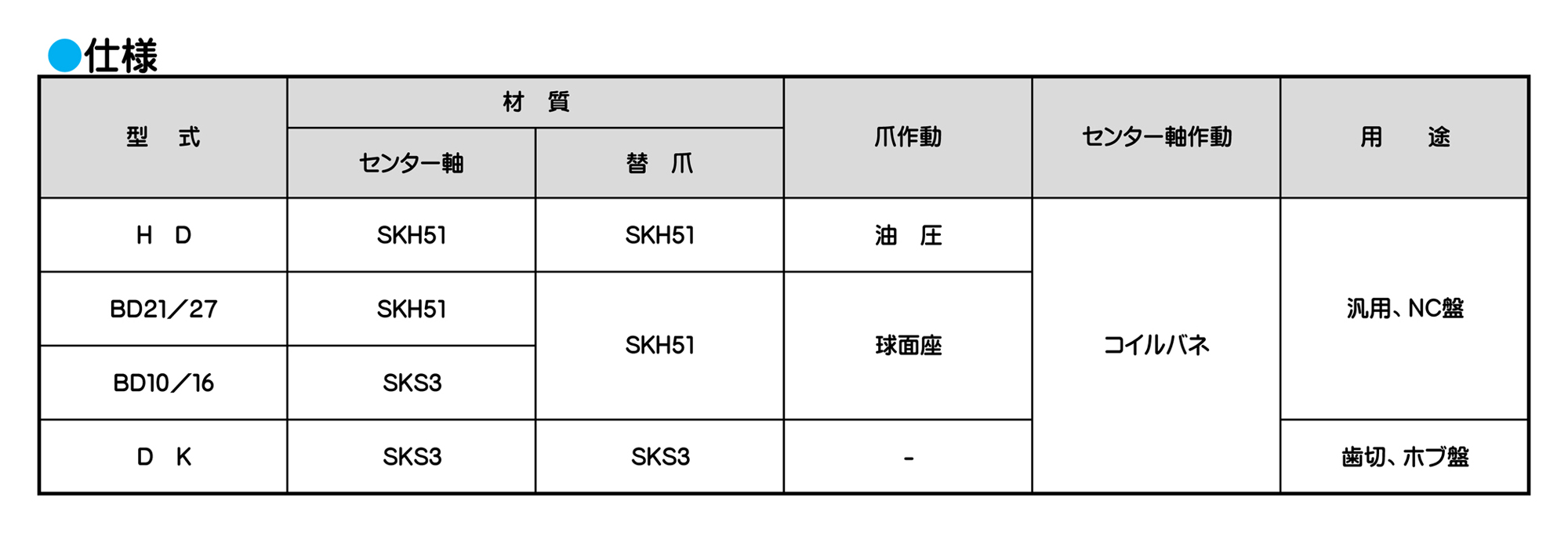
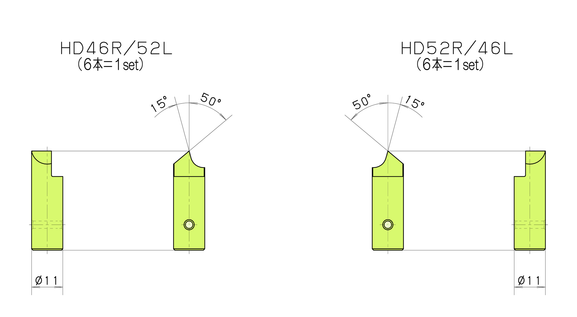
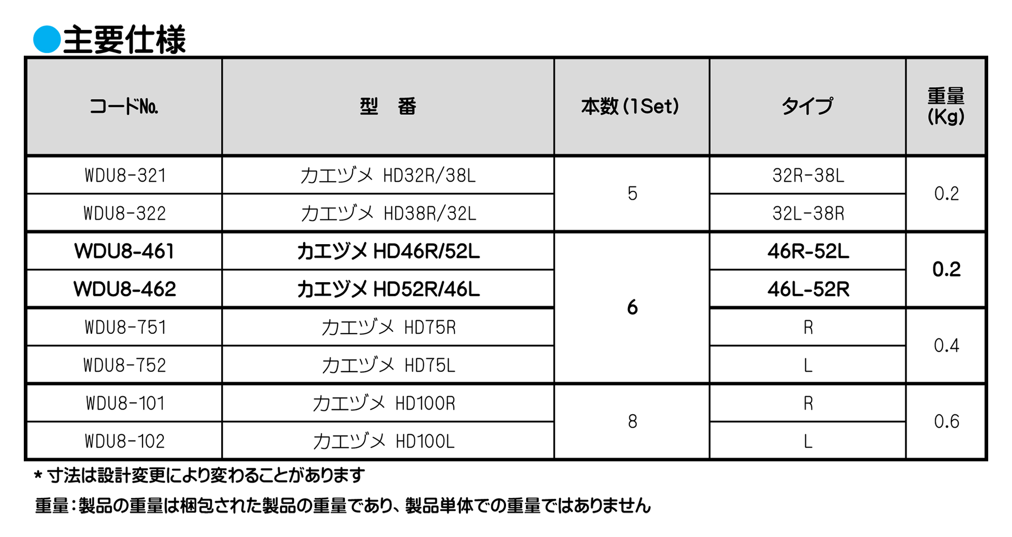
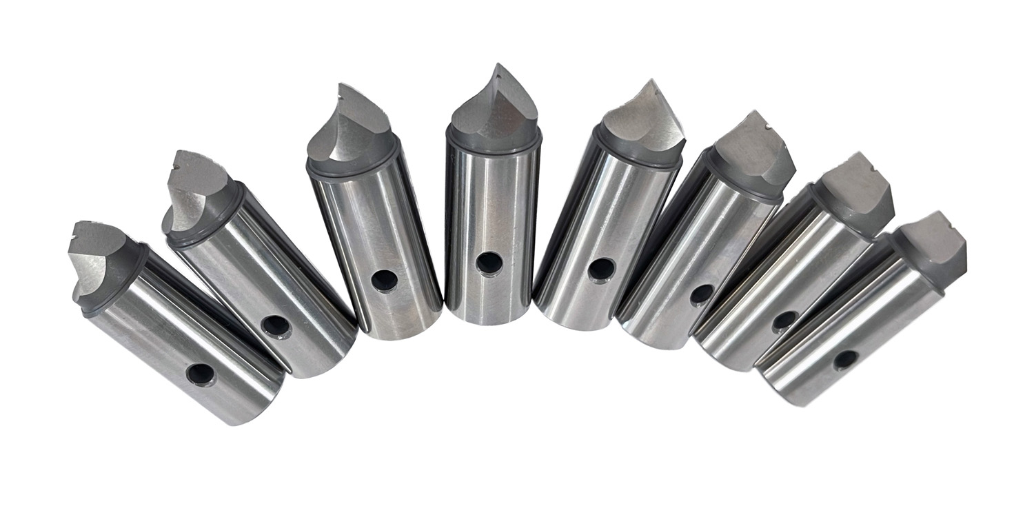
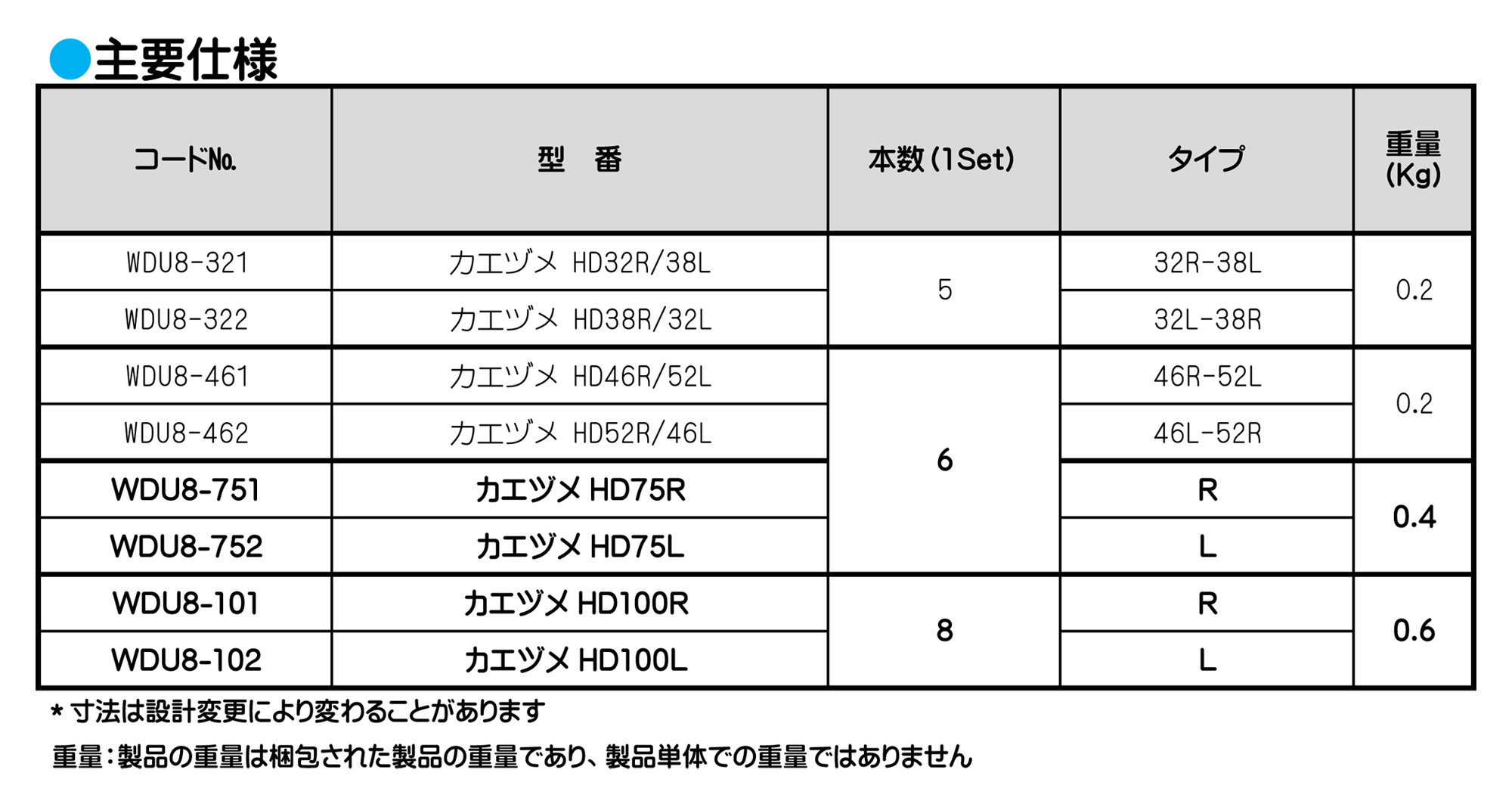
ワークドライビングセンター
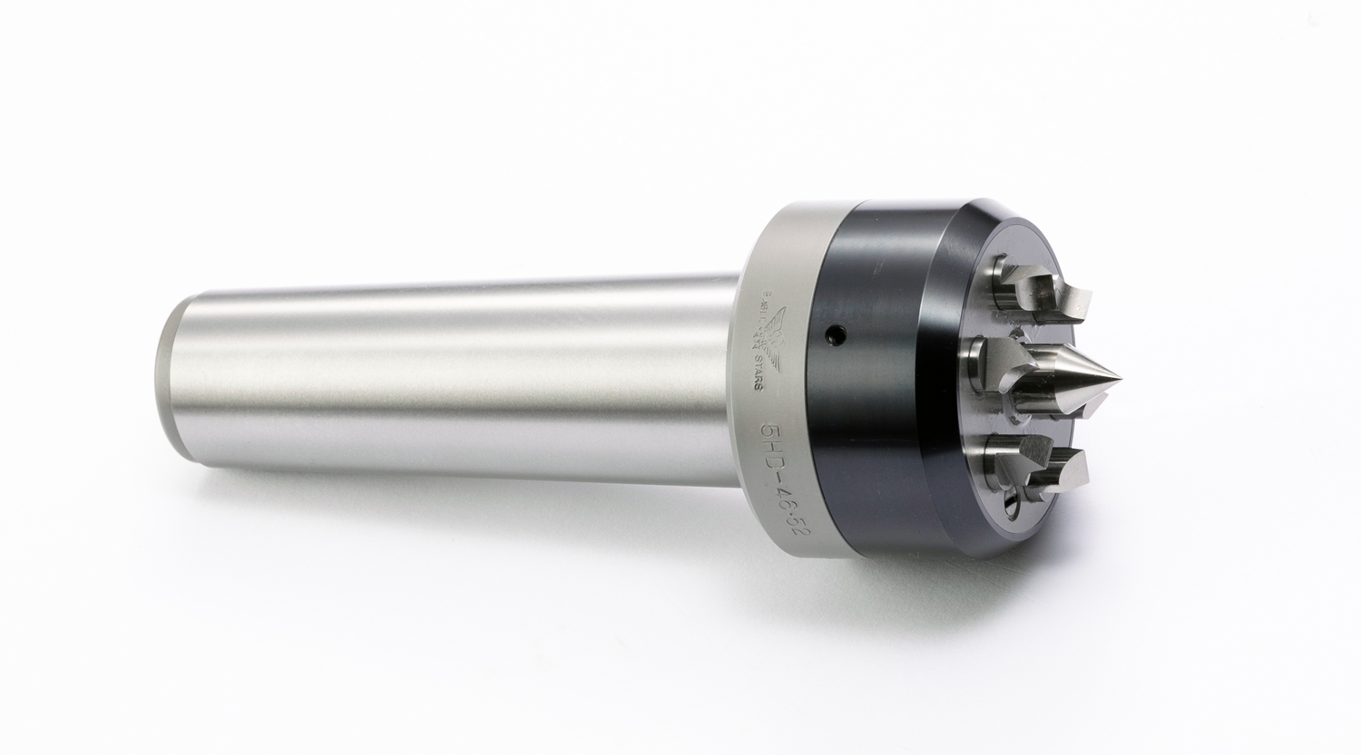
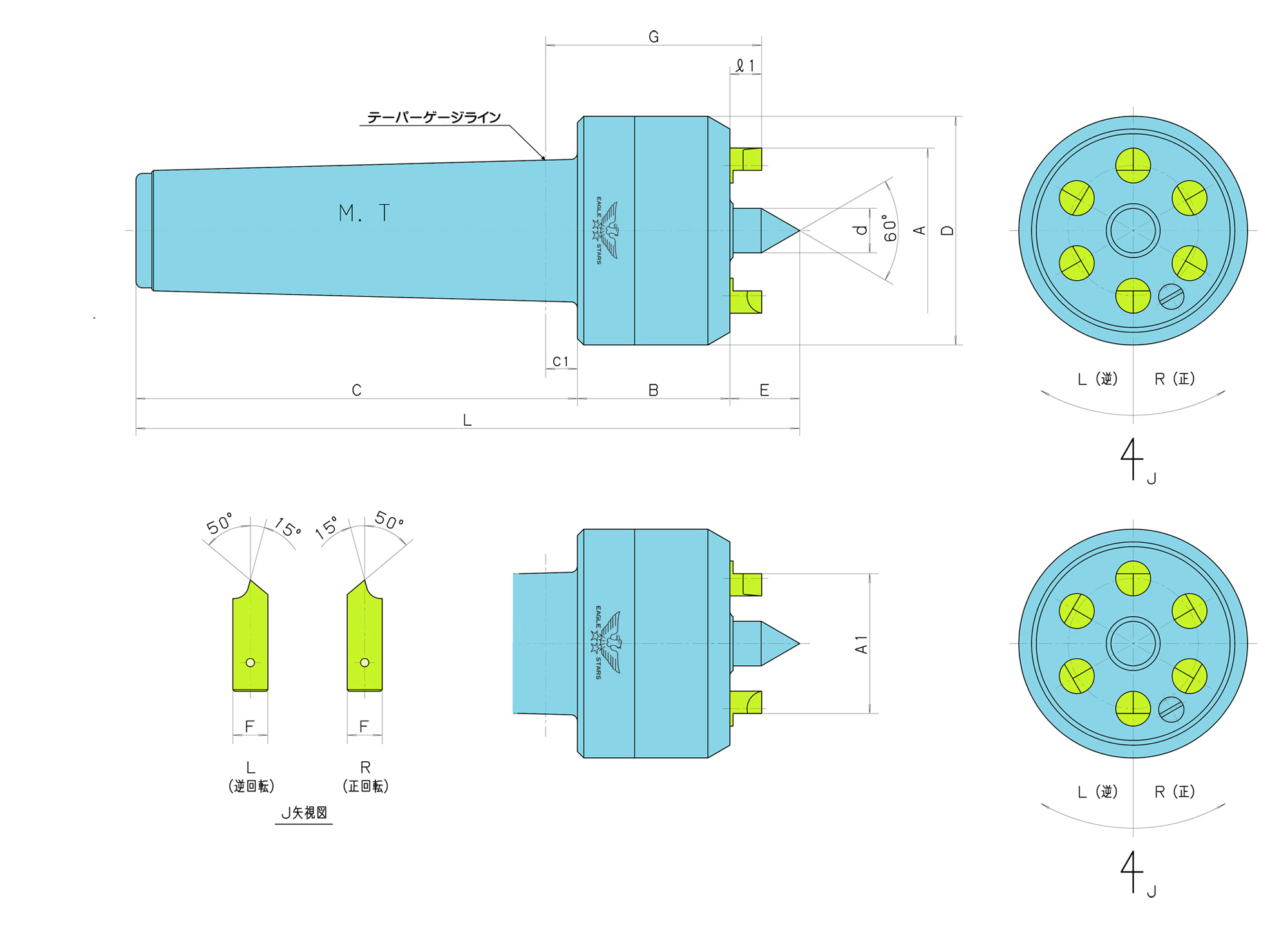
■爪作動に油圧機構を採用しており、爪が独立して作動することにより端面を均一に保持します。
■爪、センター軸の材質にハイス鋼を使用しており、高耐久性を実現しました。
ご使用について
■油圧機構用の油の補給は特に必要ありませんが、本体より爪の出先の寸法(仕様表のℓ1)が全ての爪で以下の高さになった場合、作動油を補充してください。
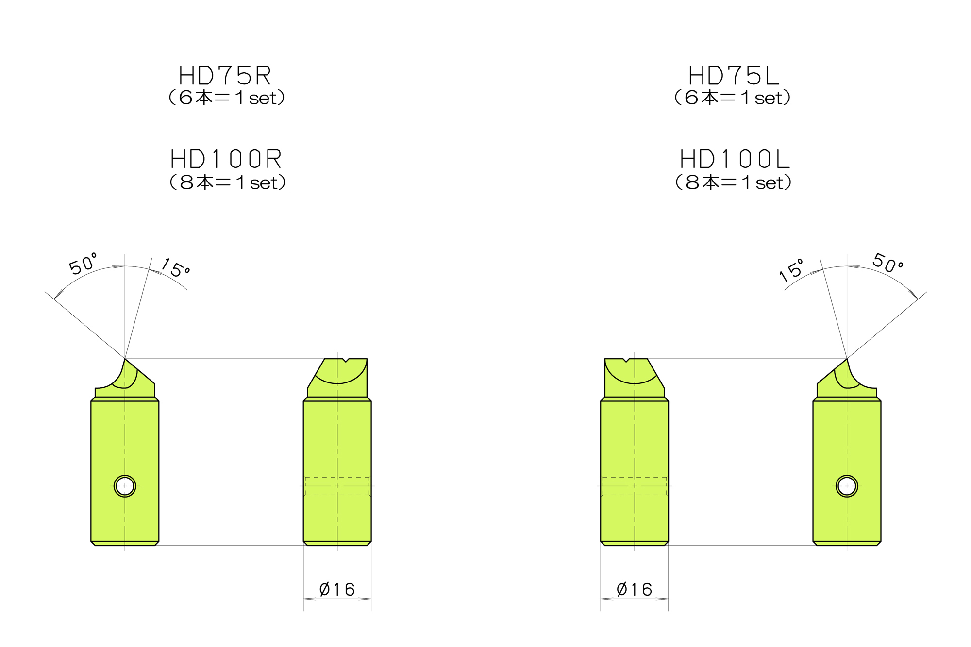
HD32/38、 HD46/52 =>7.5mm HD75、HD100 =>12.5mm
■加工物のセンター穴(口元径)は下の範囲内でご使用ください。
HD32/38=8mm以下 HD46/52=10mm以下 HD75=14mm以下
HD100=10mm以上20mm以下
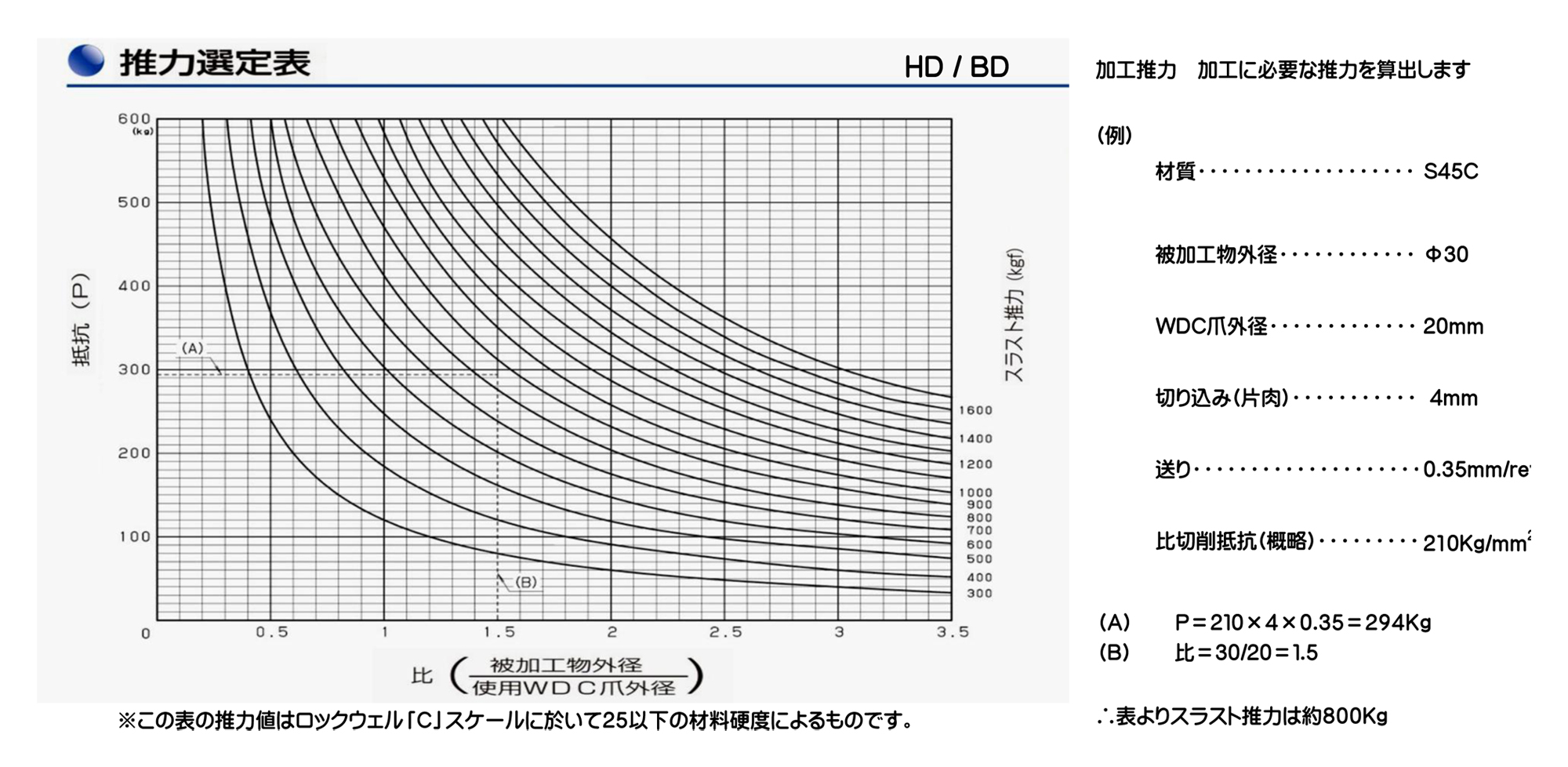
■許容スラスト推力
HD32/38=1000kgf HD46/52=1200kgf HD75=2400kgf HD100=3200kgf
■加工時の回転方向を確認し、R(正回転)、L(逆回転)をご指定ください。
■調質材等硬度の入った材料についてはお問合せください。
ワークドライビングセンター

本機種は爪作動タイプで、小径加工物の旋削に適するように開発された製品です。
■爪に加わる推力を球面座で受ける機構にしてフラット面支持とし、安定した長手方向の寸法を確保
■フラット支持により、爪作動部の耐摩耗性・駆動力を向上
■センター軸の改良により、精度の長期安定性を実現
■メンテナンス性を向上
ご使用について
■加工物のセンター穴(口元径)は2〜6mmの範囲で使用してください。
■爪が消耗、破損した場合の交換爪の用意も致しております。
■加工時の回転方向に合わせて、<R(正回転)>、<L(逆回転)>をご指定ください。スピンドルを見て、反時計回り<R(正回転)>、時計回り<L(逆回転)>。
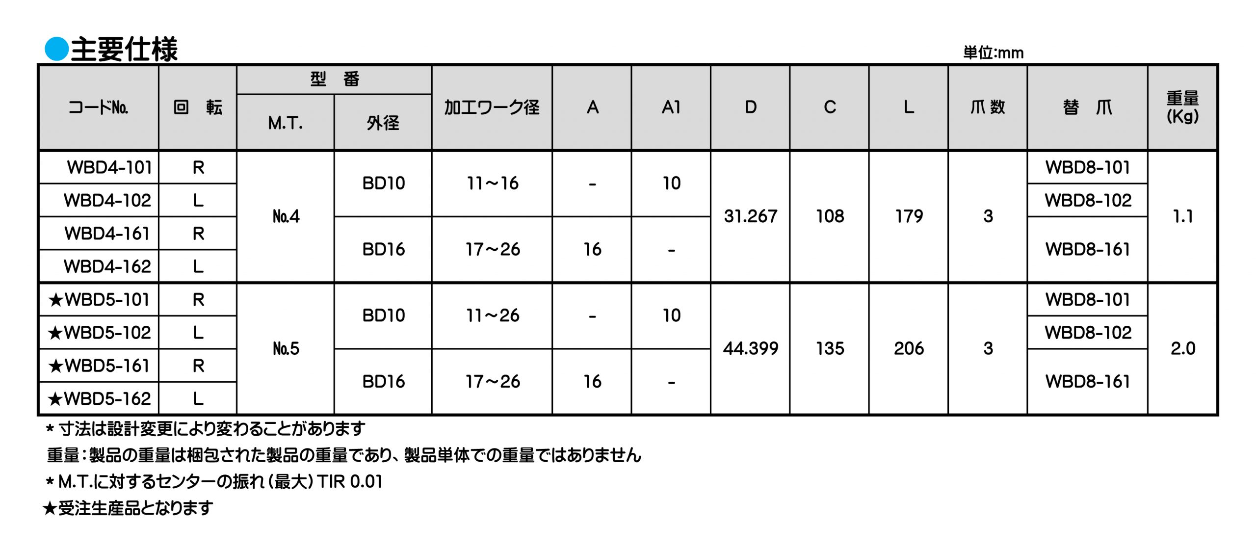
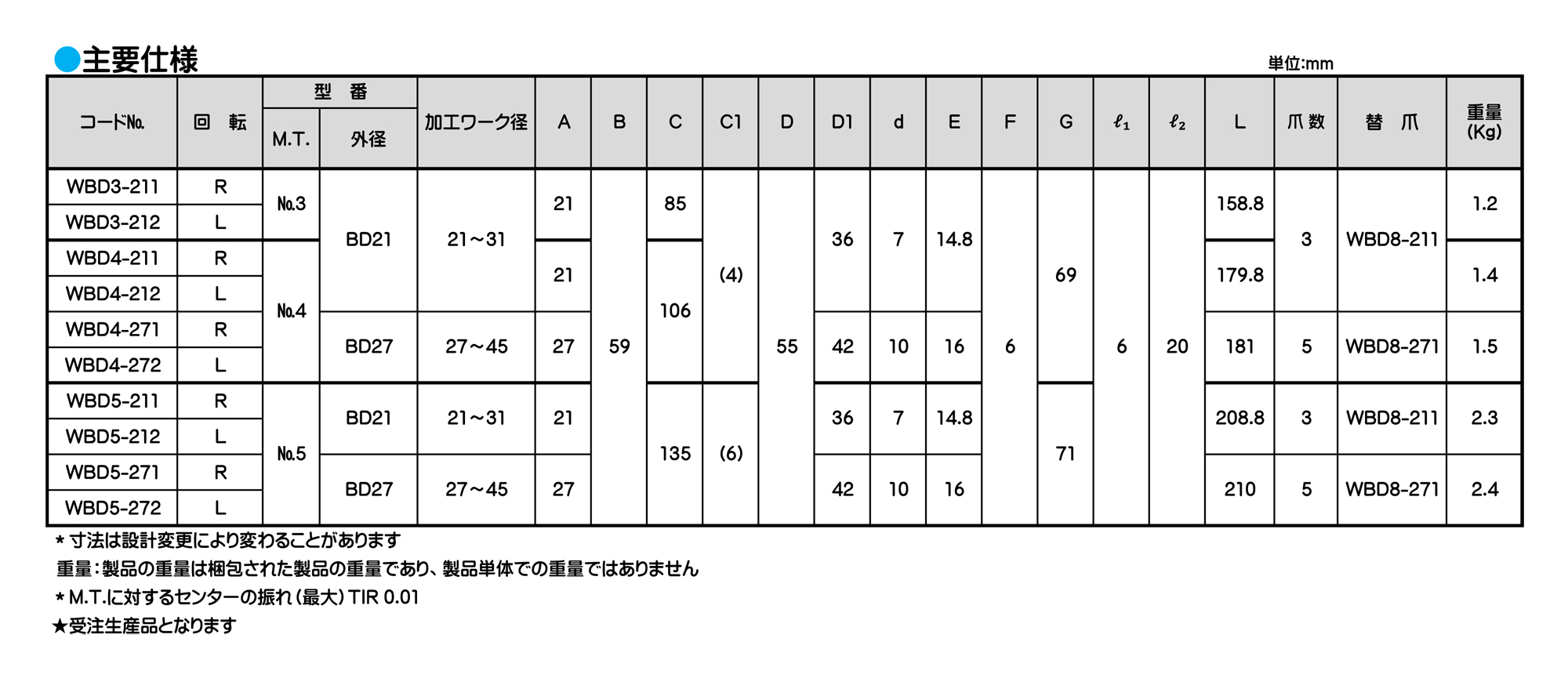
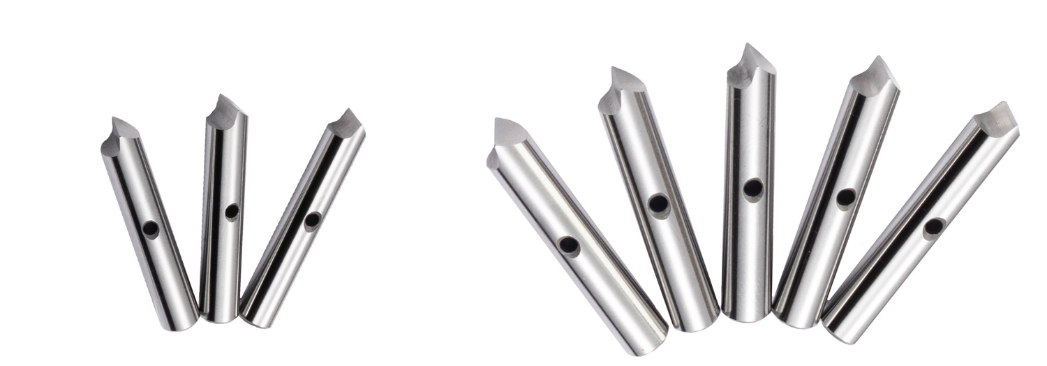
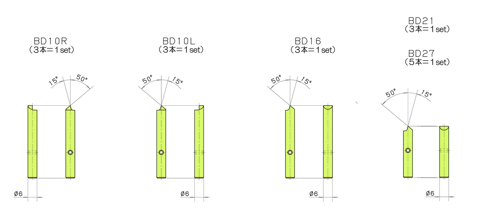
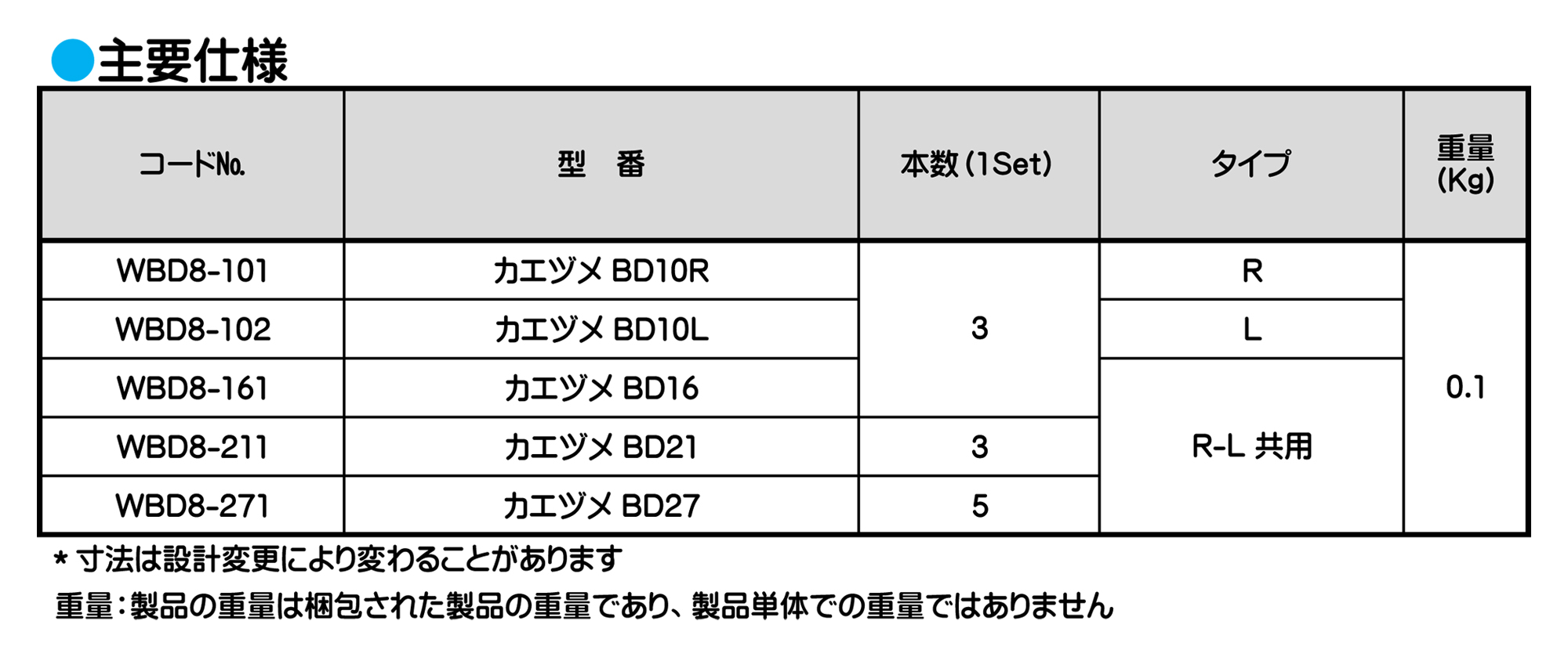
ワークドライビングセンター
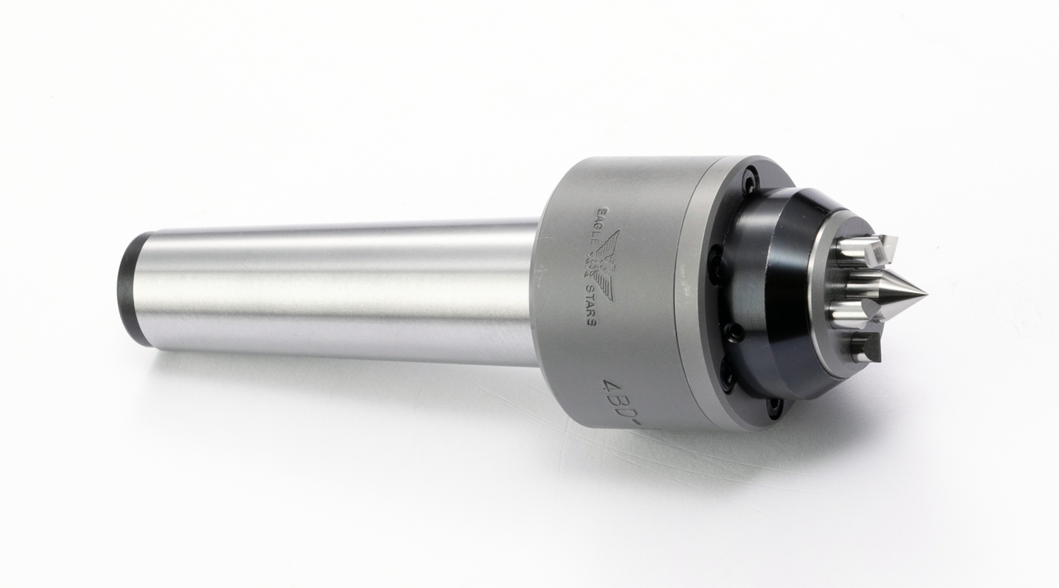
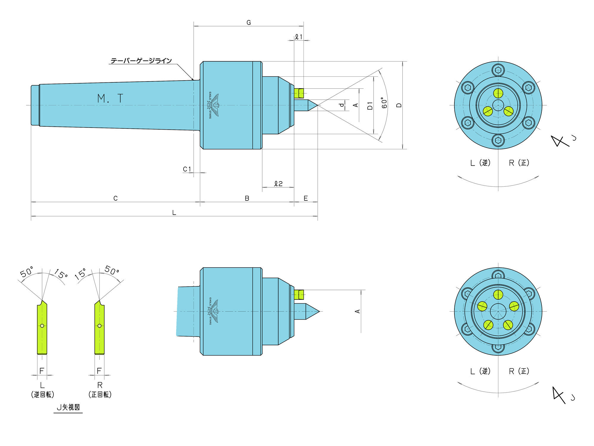
■爪に加わる推力を球面座で受ける機構とし、加工時に安定した長手方向の寸法を確保
■フラット支持により、爪作動部の耐摩耗性・駆動力を向上
■BD21は3本爪、BD27は5本爪仕様。
■メンテナンス性を向上
ご使用について
■加工物のセンター穴(口元径)は
BD21=2~6mm、BD27=2~8mmの範囲で使用してください。
■爪が消耗、破損した場合の交換爪の用意も致しております。
■加工時の回転方向に合わせて<R(正回転)>、<L(逆回転)>をご指定ください。
スピンドルを見て、反時計回り<R(正回転)>、時計回り<L(逆回転)>。
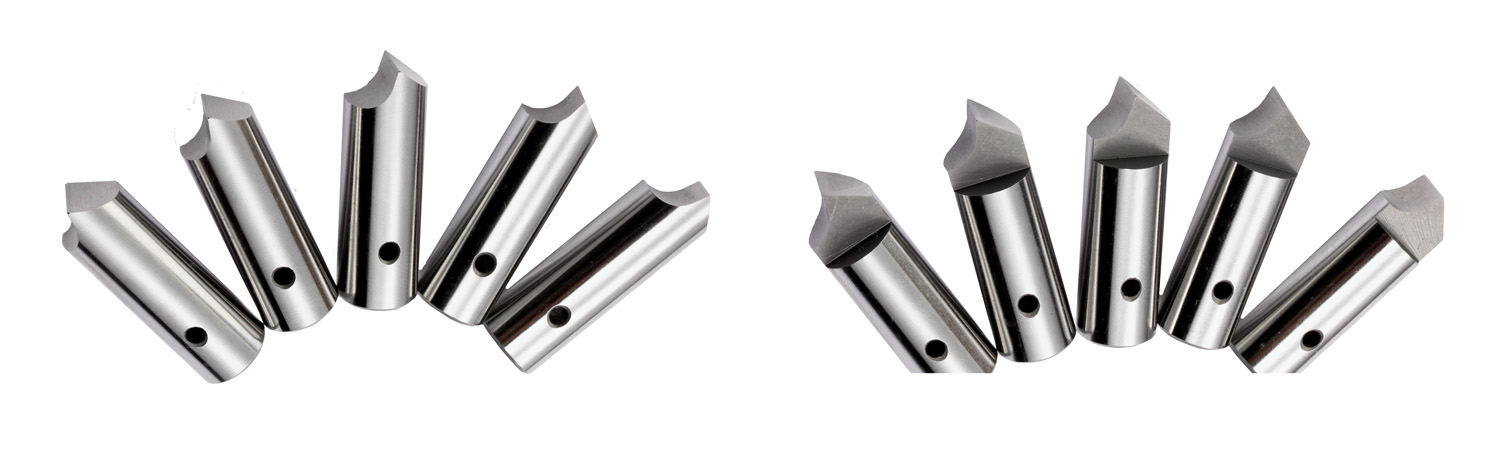
ワークドライビングセンター
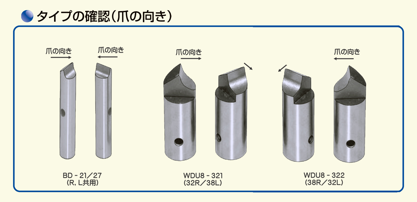
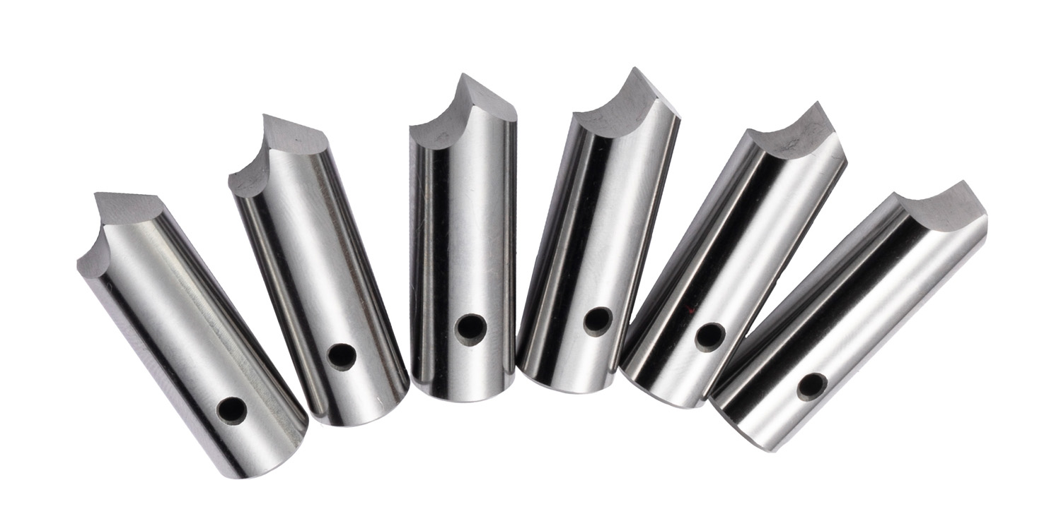
■ワークドライビングセンターの爪が消耗、破損した場合は速やかに爪を交換してご使用ください。
■替爪のご購入の際には、搭載機械の回転方向(タイプ)をご確認の上ご注文ください。
※替爪はセット販売です(1本単位での販売はしておりません)交換の際は全爪同時交換をお願いします。
回転方向について
■スピンドル(主軸)を見て、反時計回り=「R」正回転、時計回り=「L」逆回転。
ワークドライビングセンター
■ワークドライビングセンターの爪が消耗、破損した場合は速やかに爪を交換してご使用ください。
■替爪のご購入の際には、搭載機械の回転方向(タイプ)をご確認の上ご注文ください。
※替爪はセット販売です(1本単位での販売はしておりません)交換の際は全爪同時交換をお願いします。
回転方向について
■スピンドル(主軸)を見て、反時計回り=「R」正回転、時計回り=「L」逆回転。
ワークドライビングセンター
■ワークドライビングセンターの爪が消耗、破損した場合は速やかに爪を交換してご使用ください。
■替爪のご購入の際には、搭載機械の回転方向(タイプ)をご確認の上ご注文ください。
※替爪はセット販売です(1本単位での販売はしておりません)交換の際は全爪同時交換をお願いします。
回転方向について
■スピンドル(主軸)を見て、反時計回り=「R」正回転、時計回り=「L」逆回転。
ワークドライビングセンター
■ワークドライビングセンターの爪が消耗、破損した場合は速やかに爪を交換してご使用ください。
■替爪のご購入の際には、搭載機械の回転方向(タイプ)をご確認の上ご注文ください。
※替爪はセット販売です(1本単位での販売はしておりません)交換の際は全爪同時交換をお願いします。
回転方向について
■スピンドル(主軸)を見て、反時計回り=「R」正回転、時計回り=「L」逆回転。
ワークドライビングセンター
■ワークドライビングセンターの爪が消耗、破損した場合は速やかに爪を交換してご使用ください。
■替爪のご購入の際には、搭載機械の回転方向(タイプ)をご確認の上ご注文ください。
※替爪はセット販売です(1本単位での販売はしておりません)交換の際は全爪同時交換をお願いします。
回転方向について
■スピンドル(主軸)を見て、反時計回り=「R」正回転、時計回り=「L」逆回転。
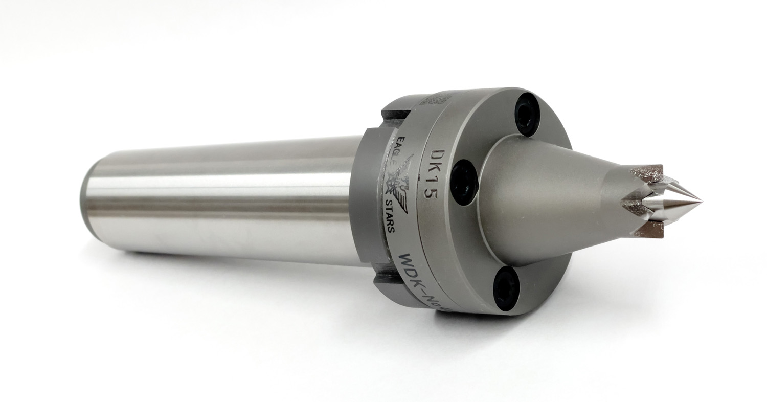
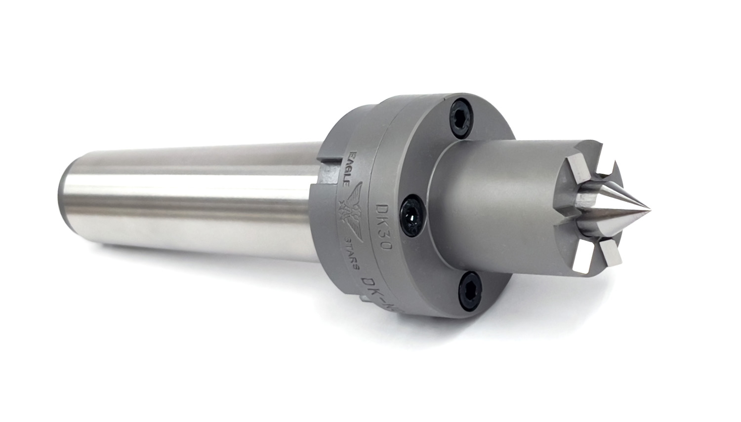
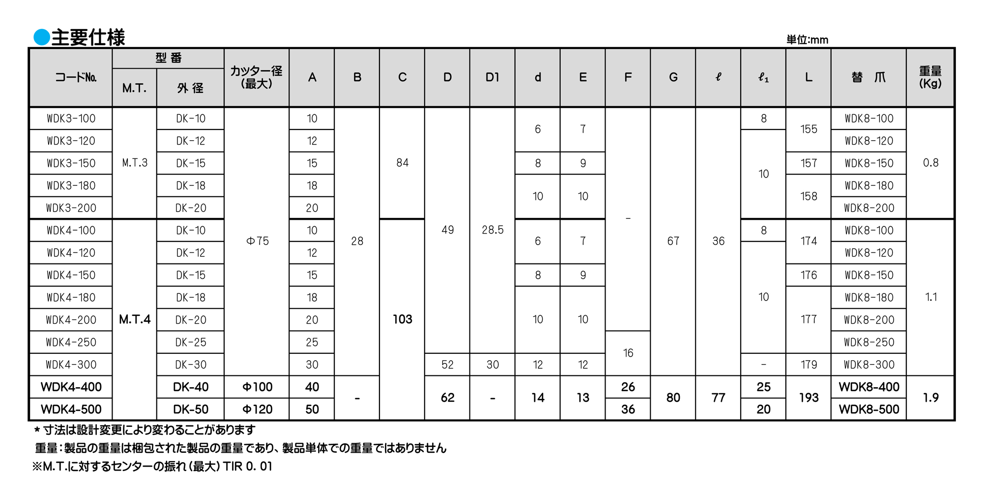
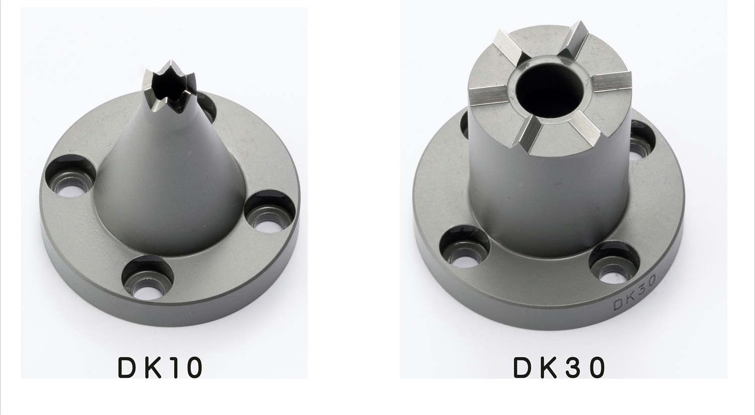
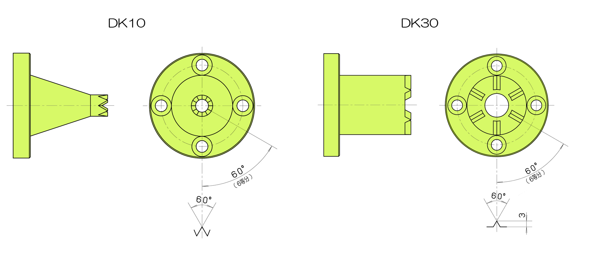
ワークドライビングセンター
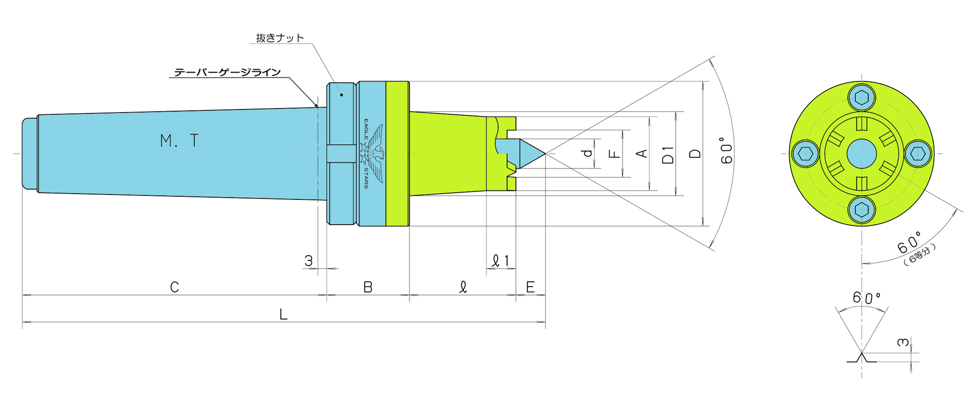
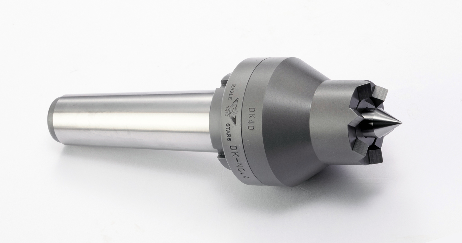
■歯切り加工、スプライン加工、キー溝加工、木工用に最適です。
■本機を使用すれば、チャックの必要がなくなります。
■両センターにて、加工物を保持するため加工物の仕上がりが最良です。
■加工物の着脱がワンタッチでできます。
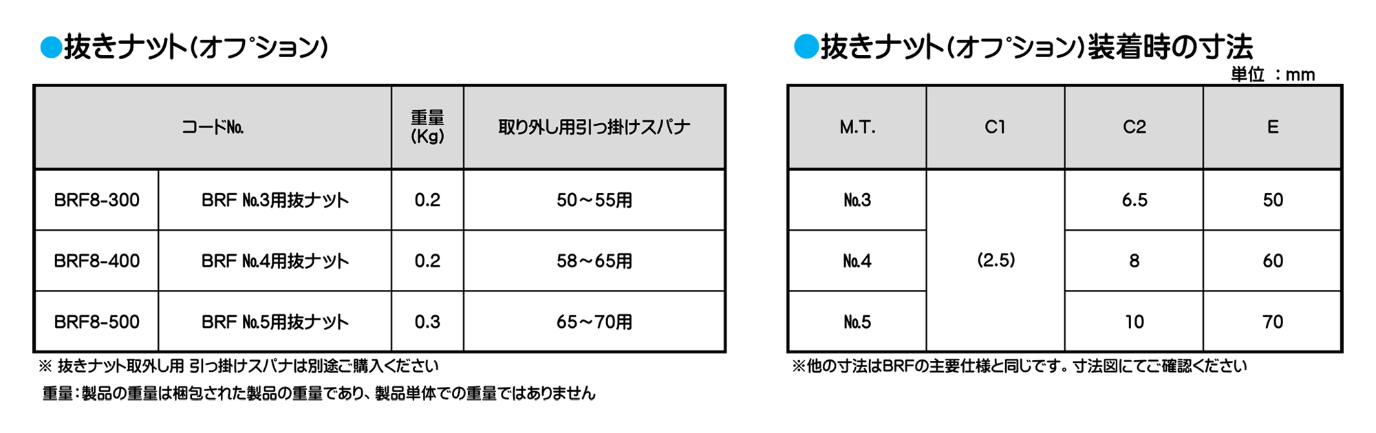
■抜きナットにより、機械よりの取り外しが簡単にできます。
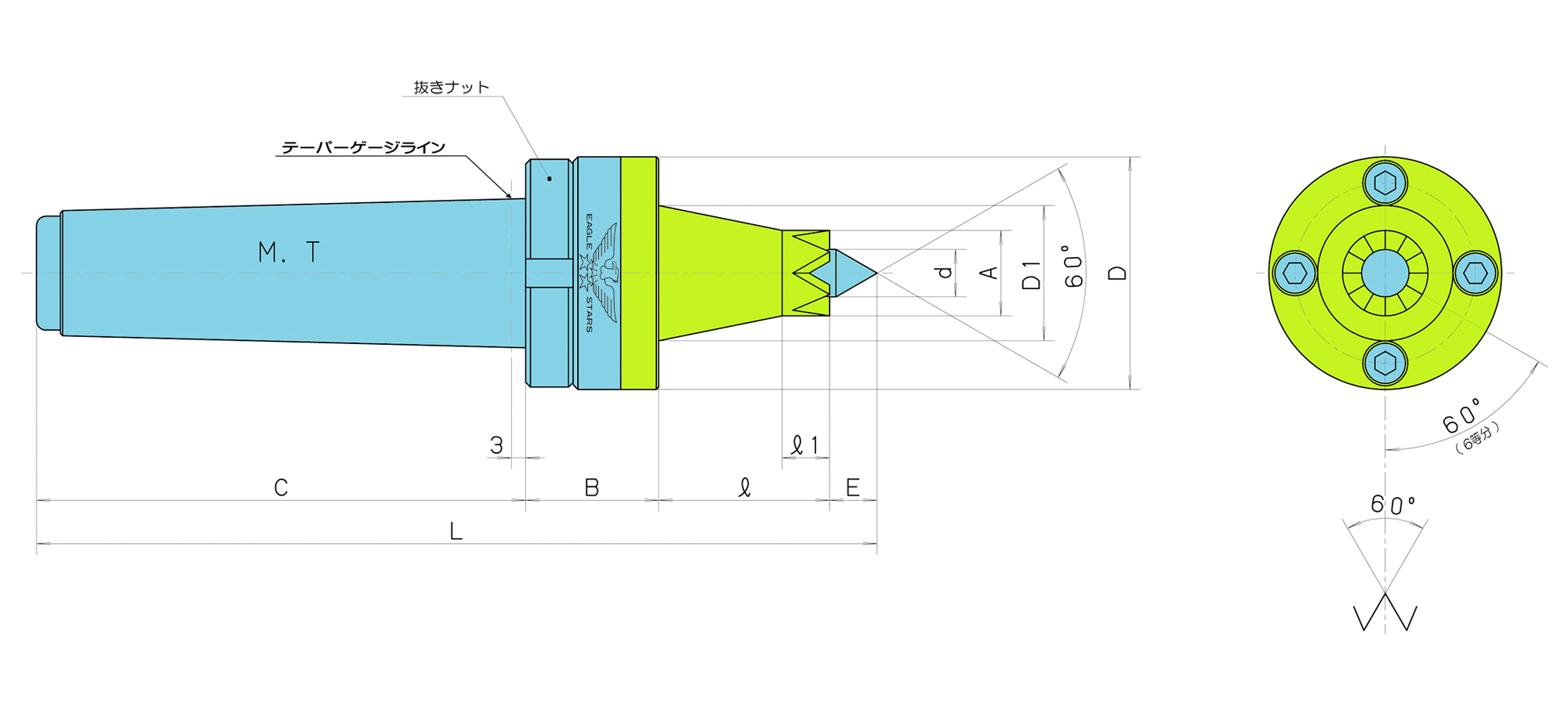
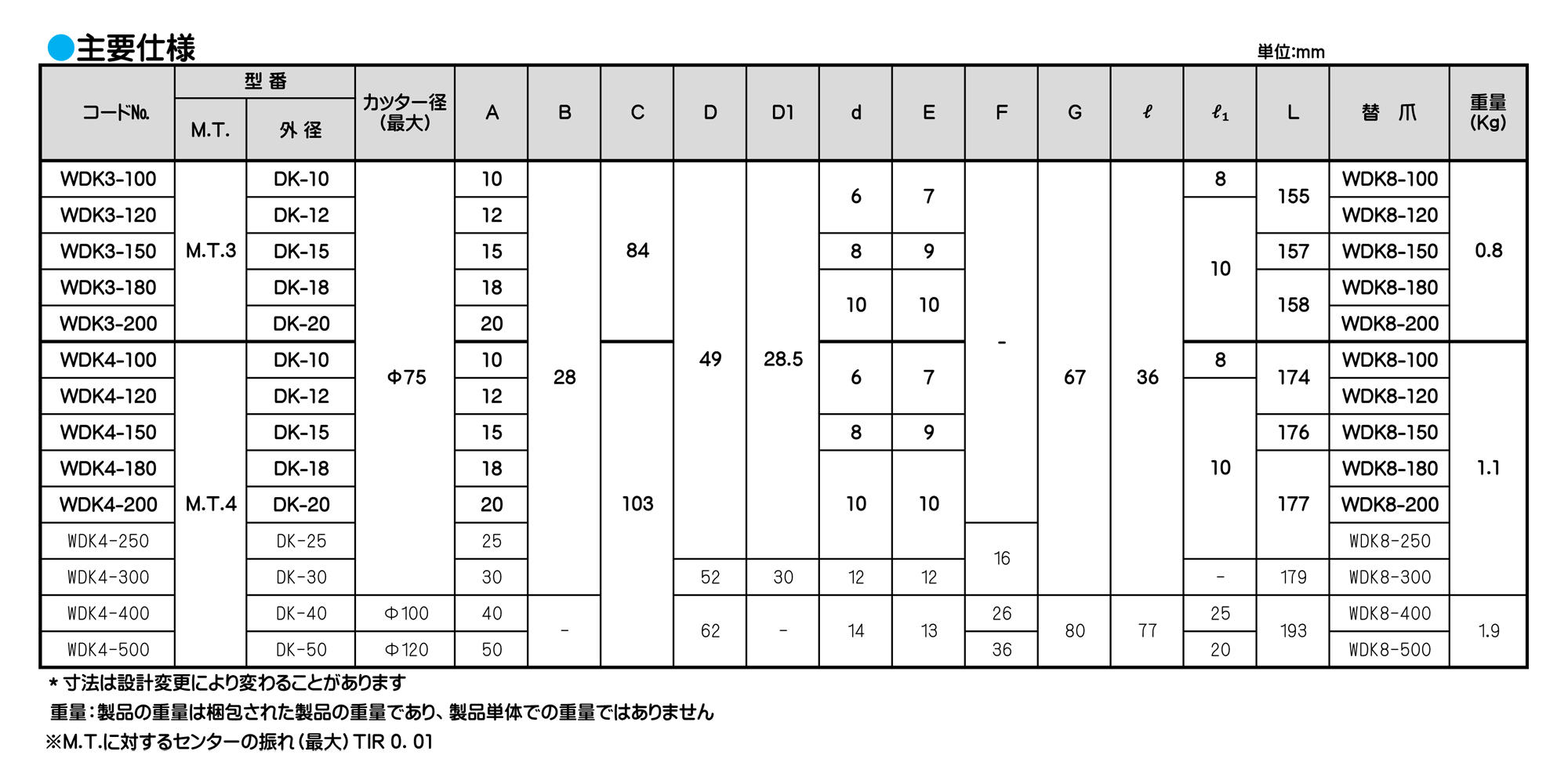
ご使用について
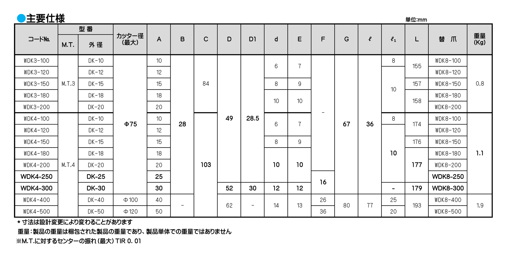
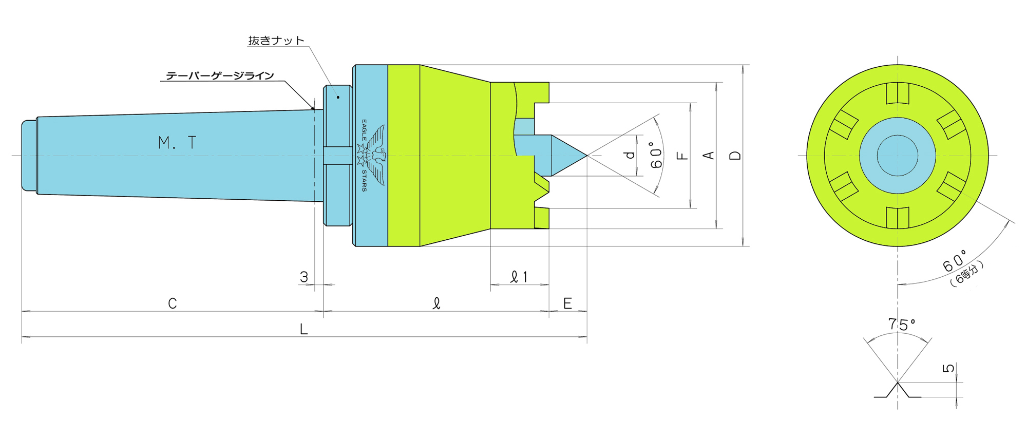
■DK10〜DK30まではカッター径最大φ75、DK40は最大φ100、DK50は最大φ120にて設計されています。
■特殊寸法の必要な場合には、寸法または加工物、図面などの提示により設計、製作いたします。
■爪が消耗、破損した場合の交換爪の用意もいたしております。
■取り外し用引掛けスパナサイズ「45〜50用」
ワークドライビングセンター
■歯切り加工、スプライン加工、キー溝加工、木工用に最適です。
■本機を使用すれば、チャックの必要がなくなります。
■両センターにて、加工物を保持するため加工物の仕上がりが最良です。
■加工物の着脱がワンタッチでできます。
■抜きナットにより、機械よりの取り外しが簡単にできます。
ご使用について
■DK10〜DK30まではカッター径最大φ75、DK40は最大φ100、DK50は最大φ120にて設計されています。
■特殊寸法の必要な場合には、寸法または加工物、図面などの提示により設計、製作いたします。
■爪が消耗、破損した場合の交換爪の用意もいたしております。
■取り外し用引掛けスパナサイズ「45〜50用」
ワークドライビングセンター
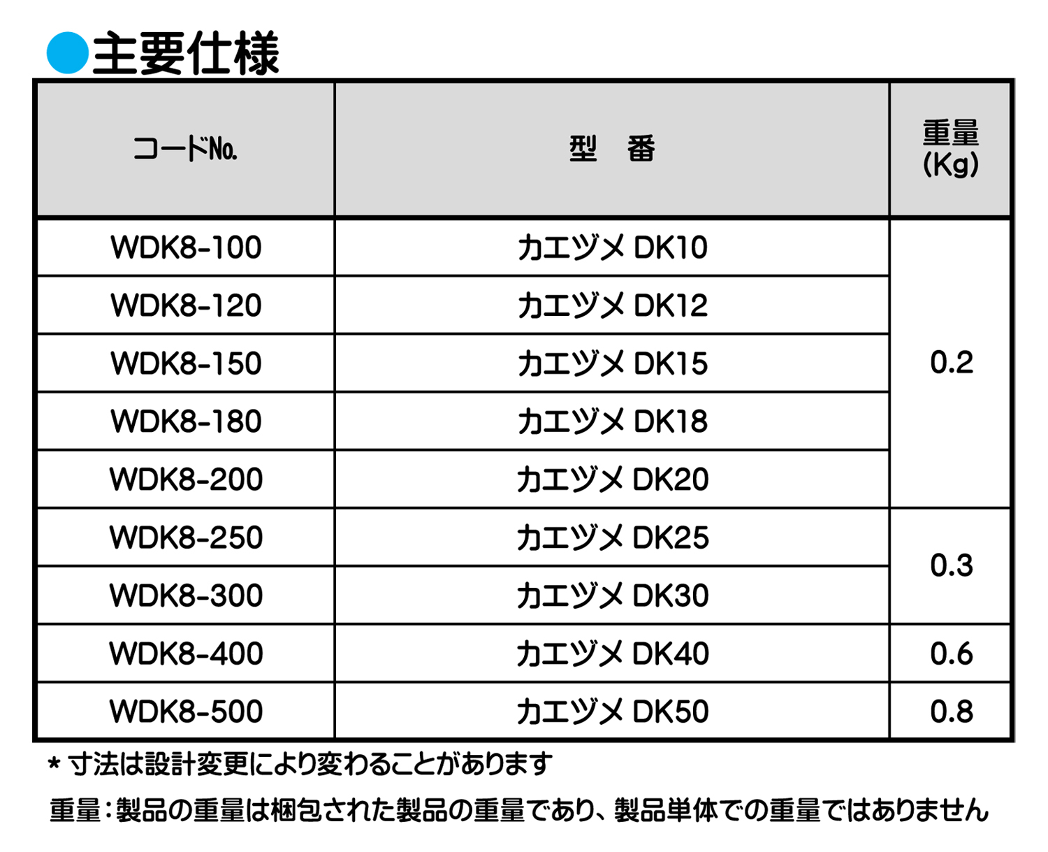
■ワークドライビングセンターの爪が消耗、破損した場合は速やかに爪を交換してご使用ください。
■替爪のご購入の際には、搭載機械の回転方向(タイプ)をご確認の上ご注文ください。
回転方向について
■スピンドル(主軸)を見て、反時計回り=「R」正回転、時計回り=「L」逆回転。
ワークドライビングセンター
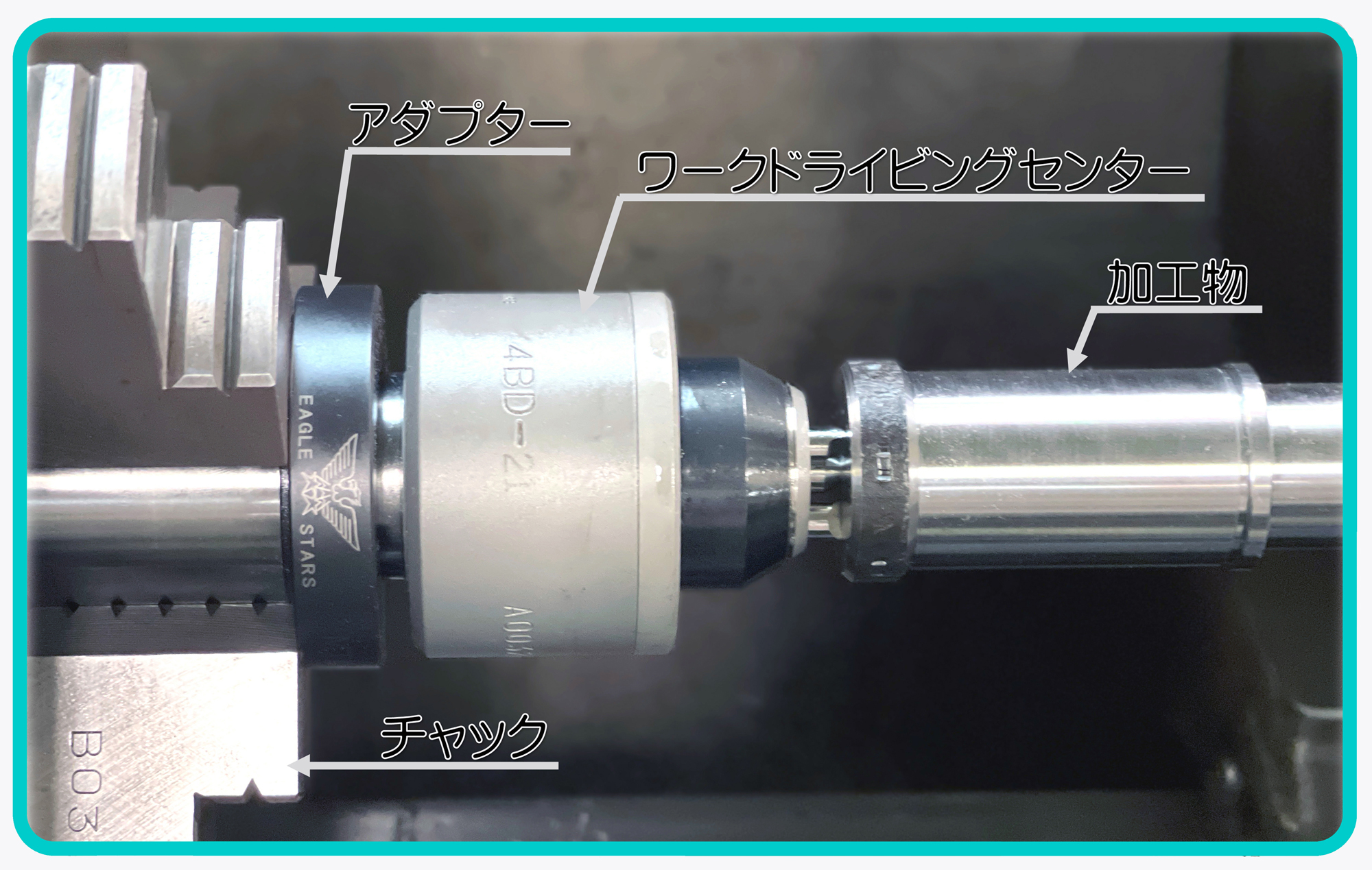
■NC機などで簡単に使用できるように外径(把握部)ストレートにしてあります。ワークドライビングセンターをご使用の場合にチャックをはずす必要がなく、チャックの生爪でアダプターの外径を把握して使用します。(全焼研磨品)
ご使用について
■アダプターにワークドライビングセンターを打ち込んでから、チャックの生爪で把握してください。
■把握後にセンターの精度確認を行ってからご使用ください。
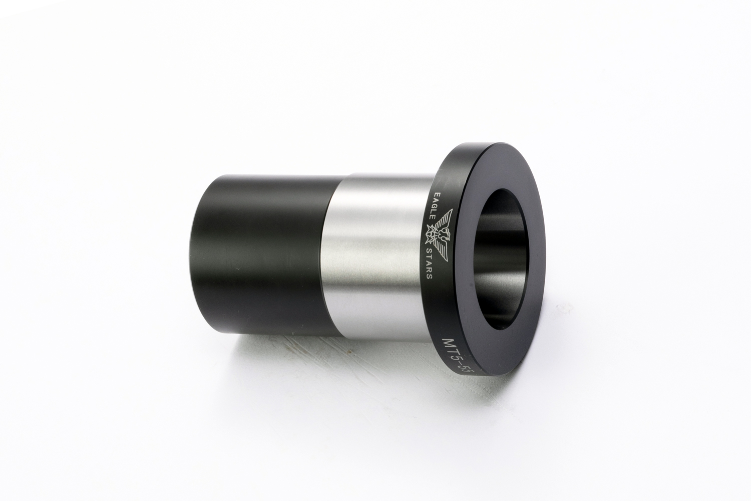
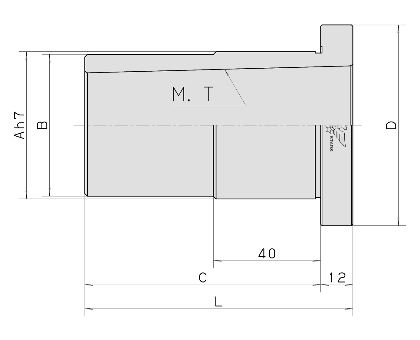
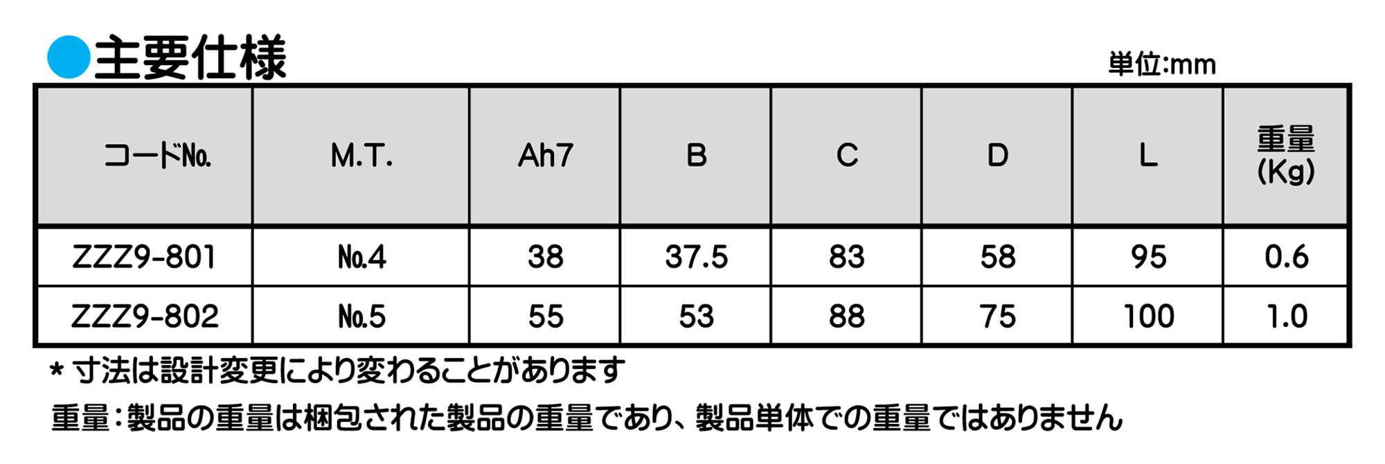
ワークドライビングセンター
■NC機などで簡単に使用できるように外径(把握部)ストレートにしてあります。ワークドライビングセンターをご使用の場合にチャックをはずす必要がなく、チャックの生爪でアダプターの外径を把握して使用します。(全焼研磨品)
ご使用について
■アダプターにワークドライビングセンターを打ち込んでから、チャックの生爪で把握してください。
■把握後にセンターの精度確認を行ってからご使用ください。
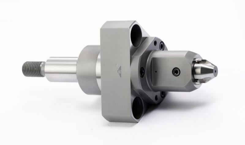
ワークドライビングセンター
特殊品
フランジタイプ
■この製品は受注生産品となります。
ワークドライビングセンター
※参考コンビネーションチャック用
■この製品は受注生産品となります。
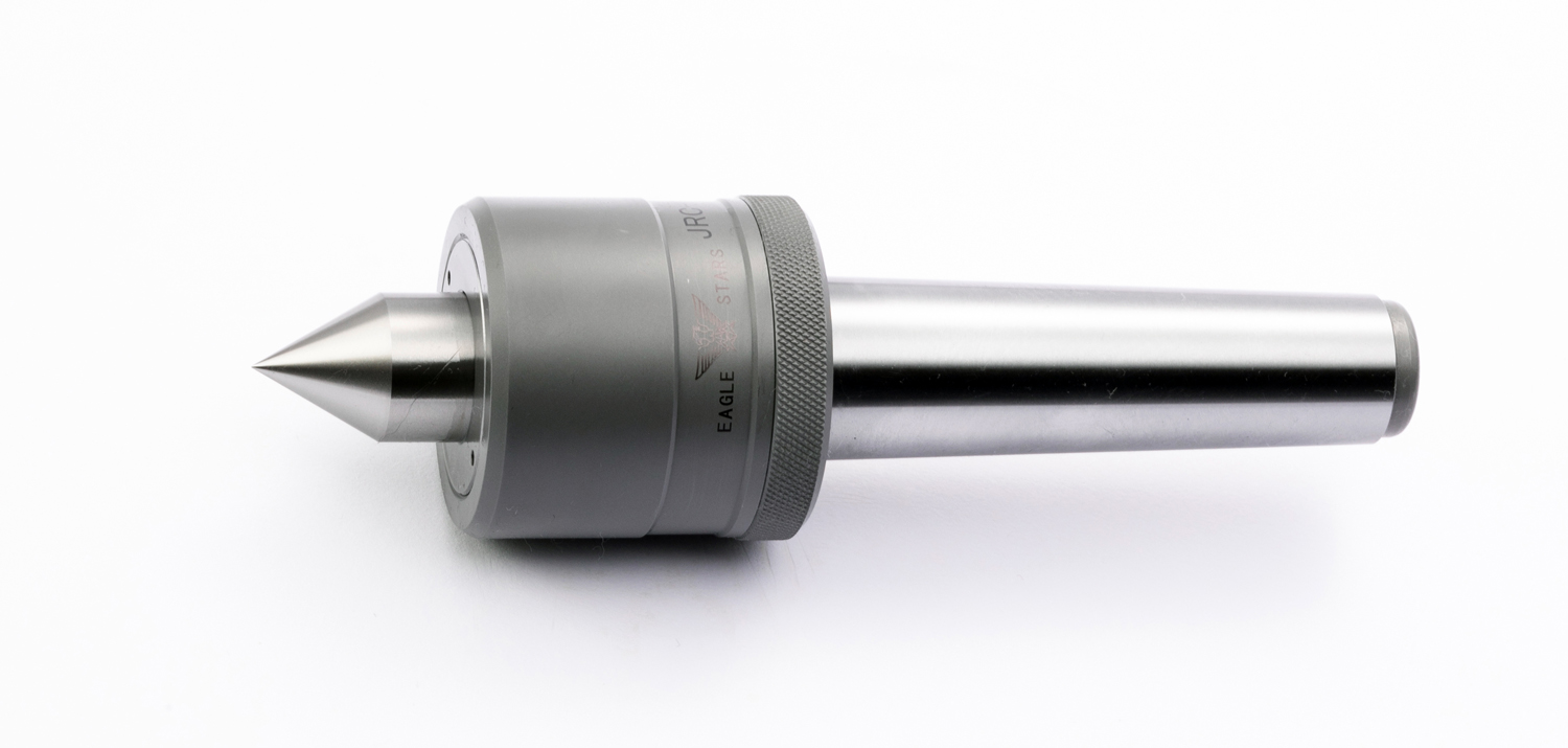
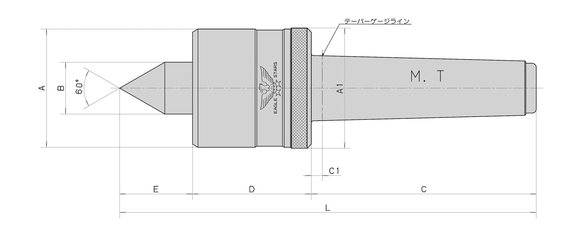
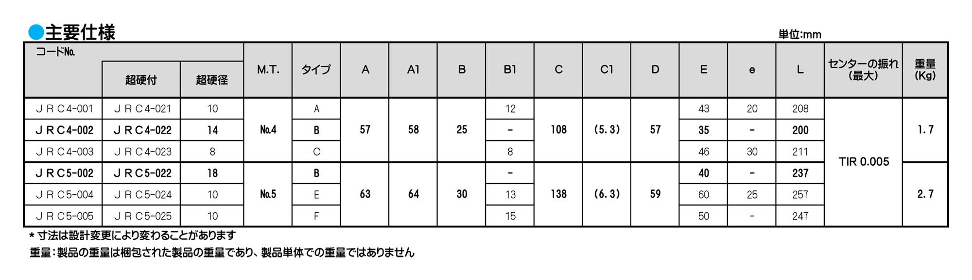
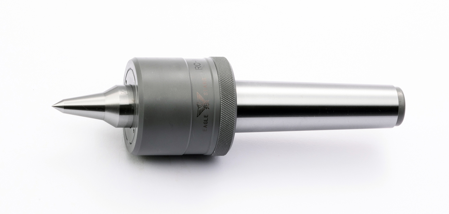
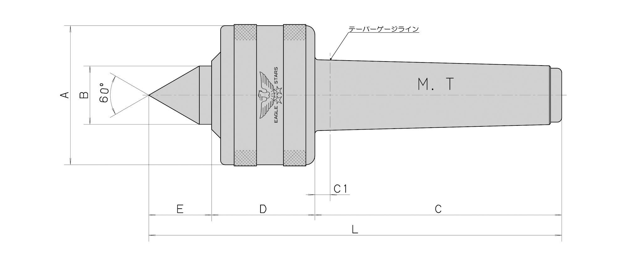
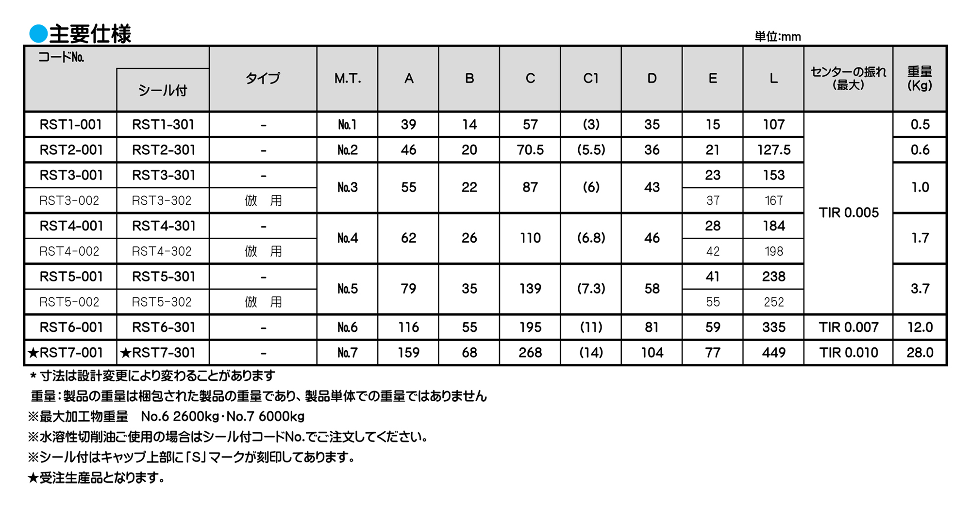
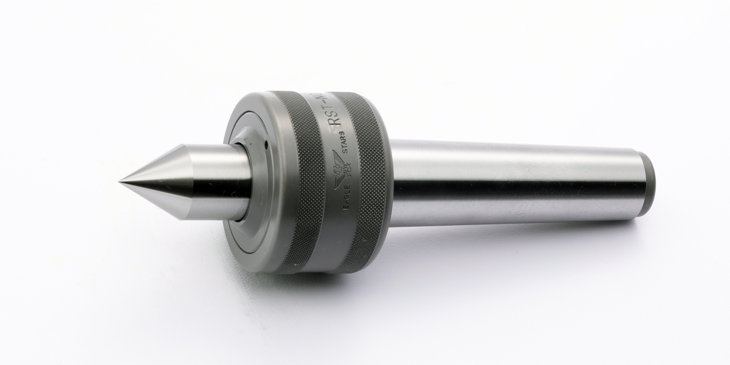
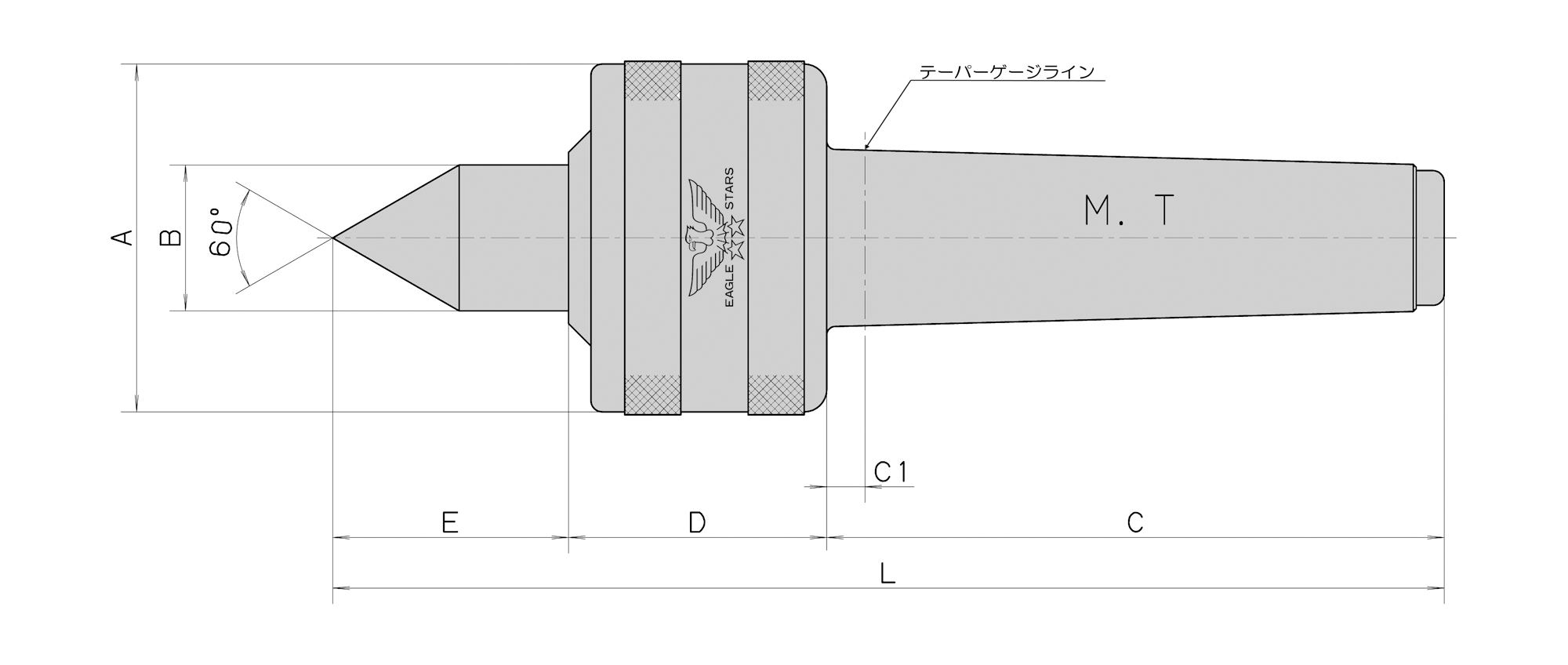
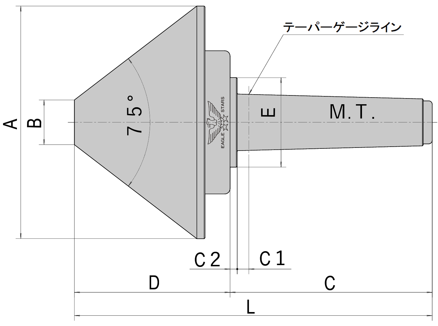
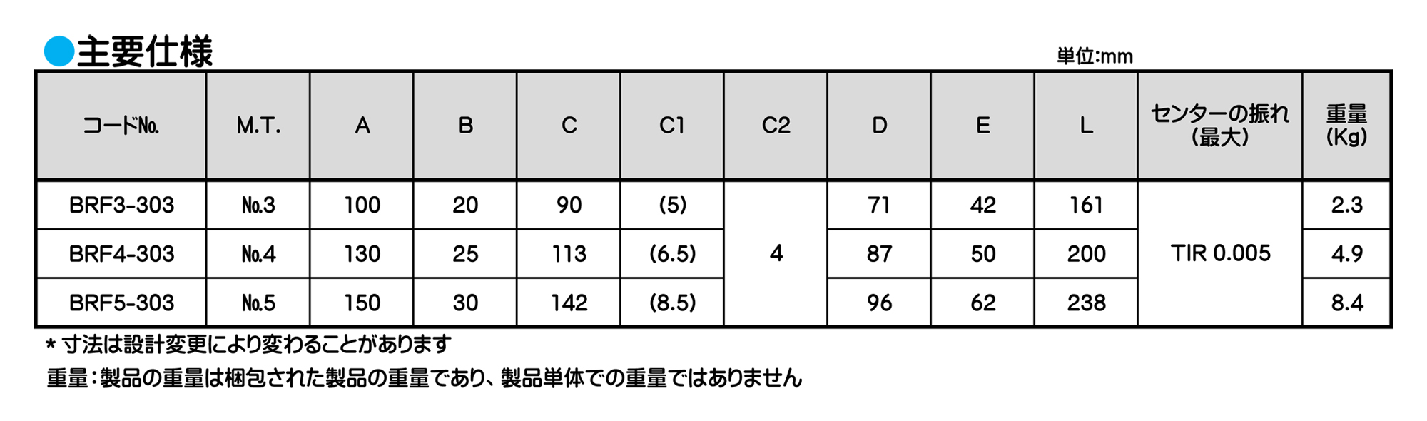
傘型回転センター

傘型回転センター
傘型回転センター
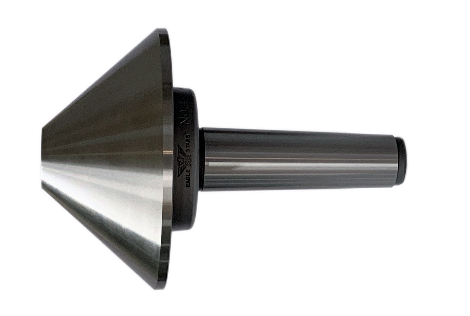
■旋盤、円筒研削盤に使用されます。
■パイプ状、リング状、薄物の加工物のセンター押し工具として用いられます。
■本製品の内部にはテーパローラベアリング、スラストベアリング、ボールベアリング各1ケの3種類を使用しています。
◆研削盤に使用する場合には、高精度のアンギュラベアリング仕様のタイプを別注品にて製作いたします。
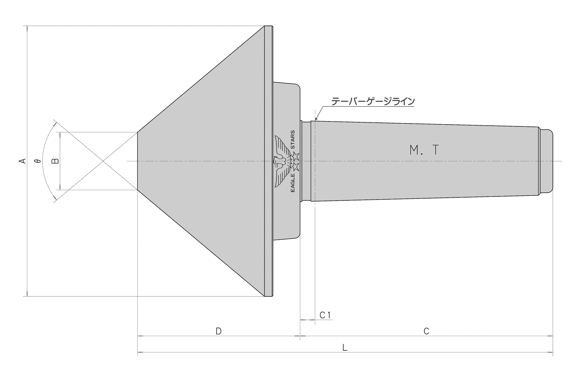
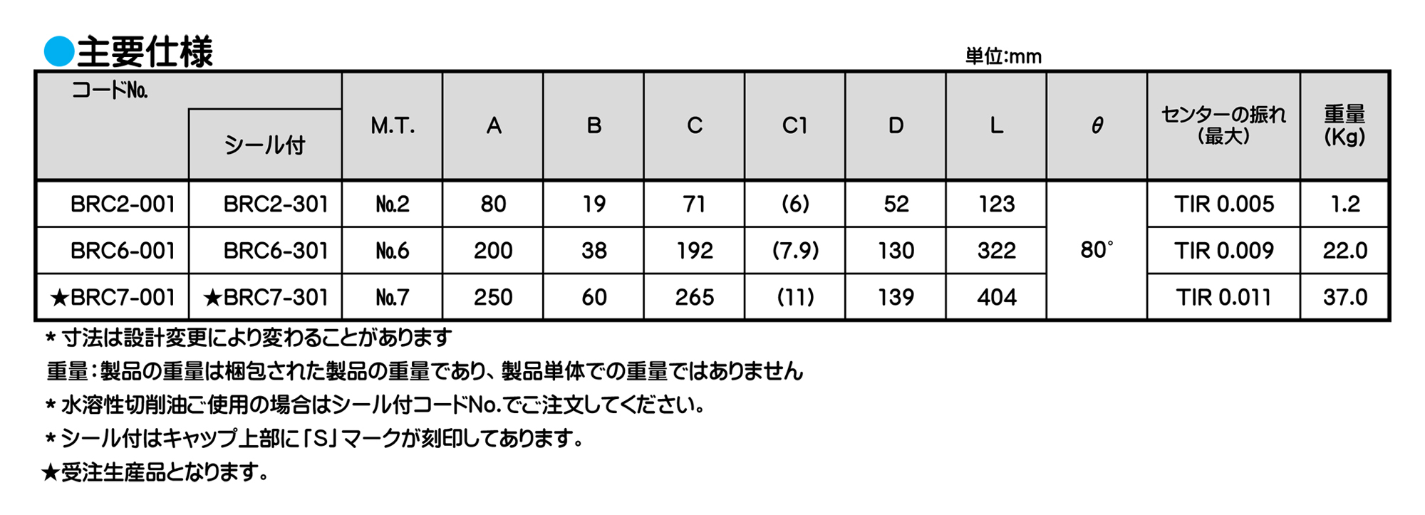
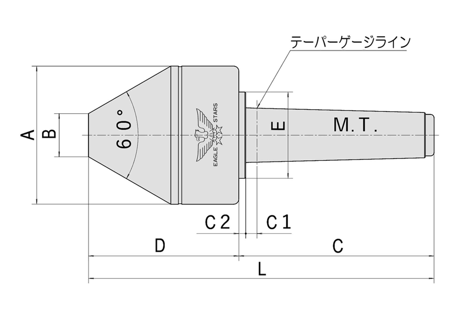
◆研削盤によっては、テーパー基準径と本体との間のC1寸法が長い場合があります。 この場合はシャンク部分が特殊になりますので、寸法ご指示ください。
※ご注意:抜きナット付心押し台には使用できません
■取付け機械の心押し台に取り外し用の抜きナットが付いている場合、抜きナットでの取り外しはできません。構造上、本体部がシャンク部から抜け落ちる事があります。
■頭部(回転部)のMTシャンク側に打撃、衝撃等を加えないでください。本体部がシャンク部から抜け落ちるおそれがあります。
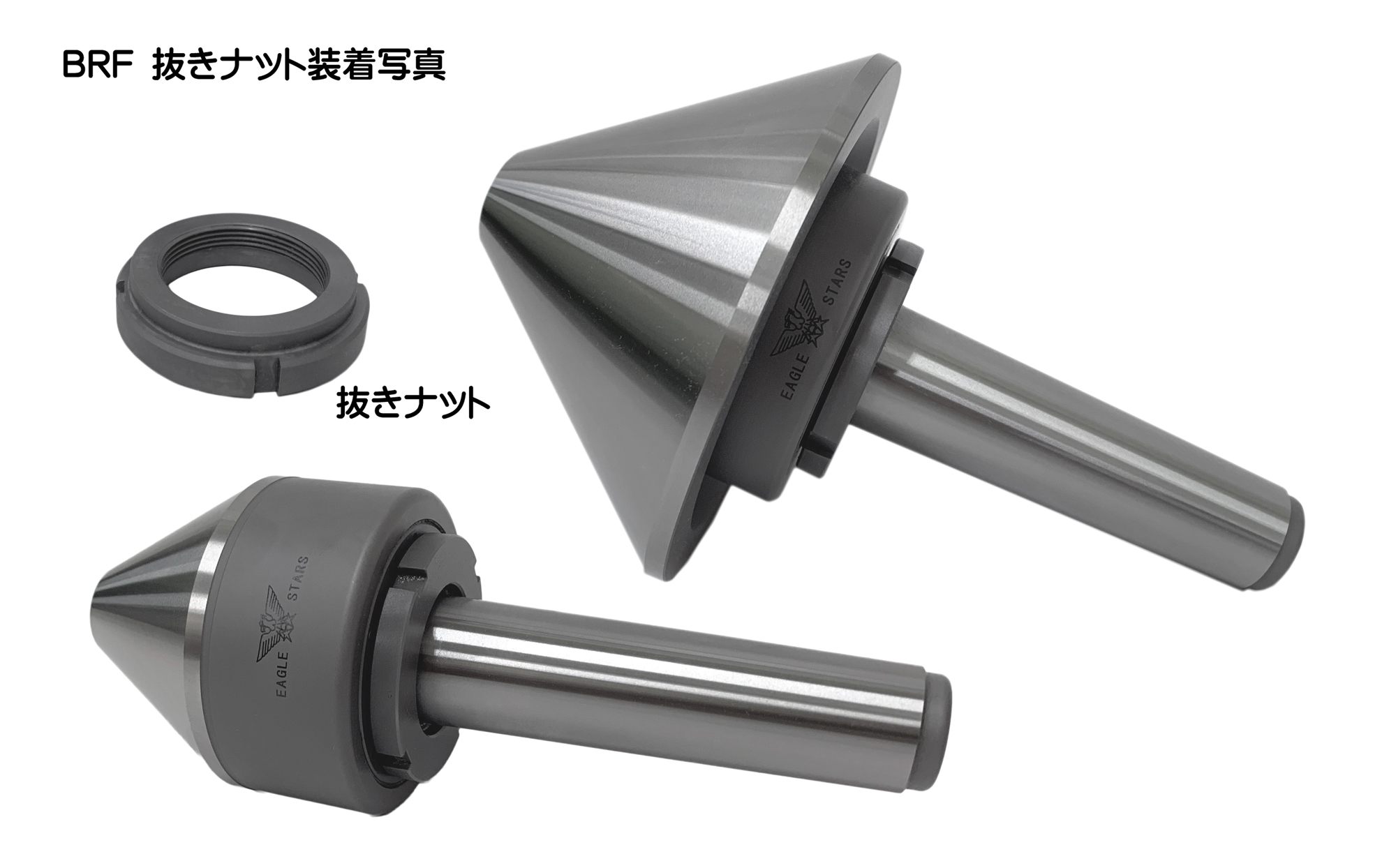
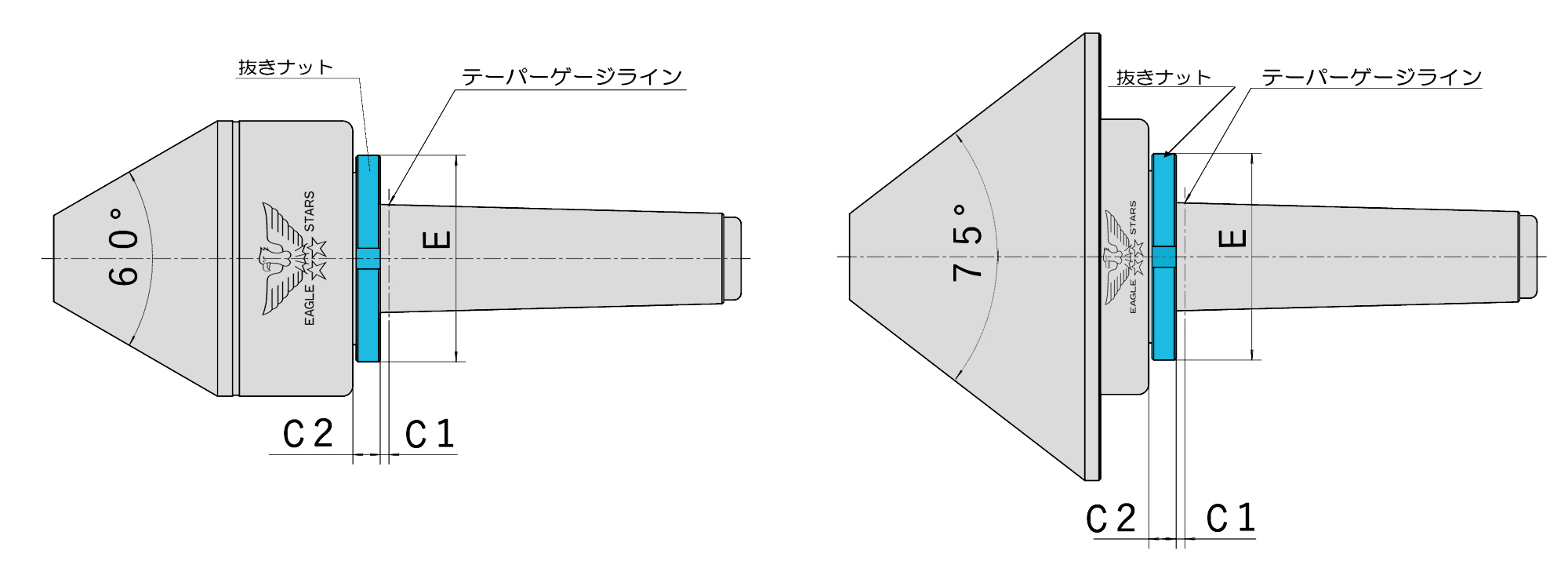
傘型回転センター
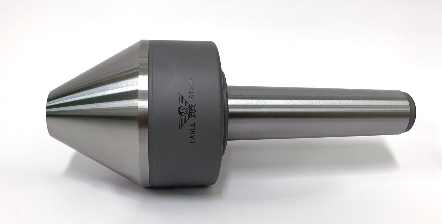
■パイプ状、リング状、薄物の加工物のセンター押しとして用いられます。
■本機種は防浸対策シールを装備しております。
■抜きナット付心押台からの取外しに対応しております。
■本製品の内部にはテーパローラベアリング、スラストベアリング、ニードルベアリング各1ケの3種類を使用しています。
■オプションにて抜きナットが装着可能です。
◆研削盤に使用する場合には、高精度のアンギュラベアリング仕様を別注品にて製作いたします。
◆取付機械や研削盤によっては、テーパー基準径と本体との間のC1寸法が長い場合があります。この場合はシャンク部分が特殊になりますので、寸法をご指示下さい。
傘型回転センター
■パイプ状、リング状、薄物の加工物のセンター押しとして用いられます。
■本機種は防浸対策シールを装備しております。
■抜きナット付心押台からの取外しに対応しております。
■本製品の内部にはテーパローラベアリング、スラストベアリング、ニードルベアリング各1ケの3種類を使用しています。
■オプションにて抜きナットが装着可能です。
◆研削盤に使用する場合には、高精度のアンギュラベアリング仕様を別注品にて製作いたします。
◆取付機械や研削盤によっては、テーパー基準径と本体との間のC1寸法が長い場合があります。この場合はシャンク部分が特殊になりますので、寸法をご指示下さい。
傘型回転センター
傘型回転センター
■心押し台の抜きナットの有無をご確認ください。
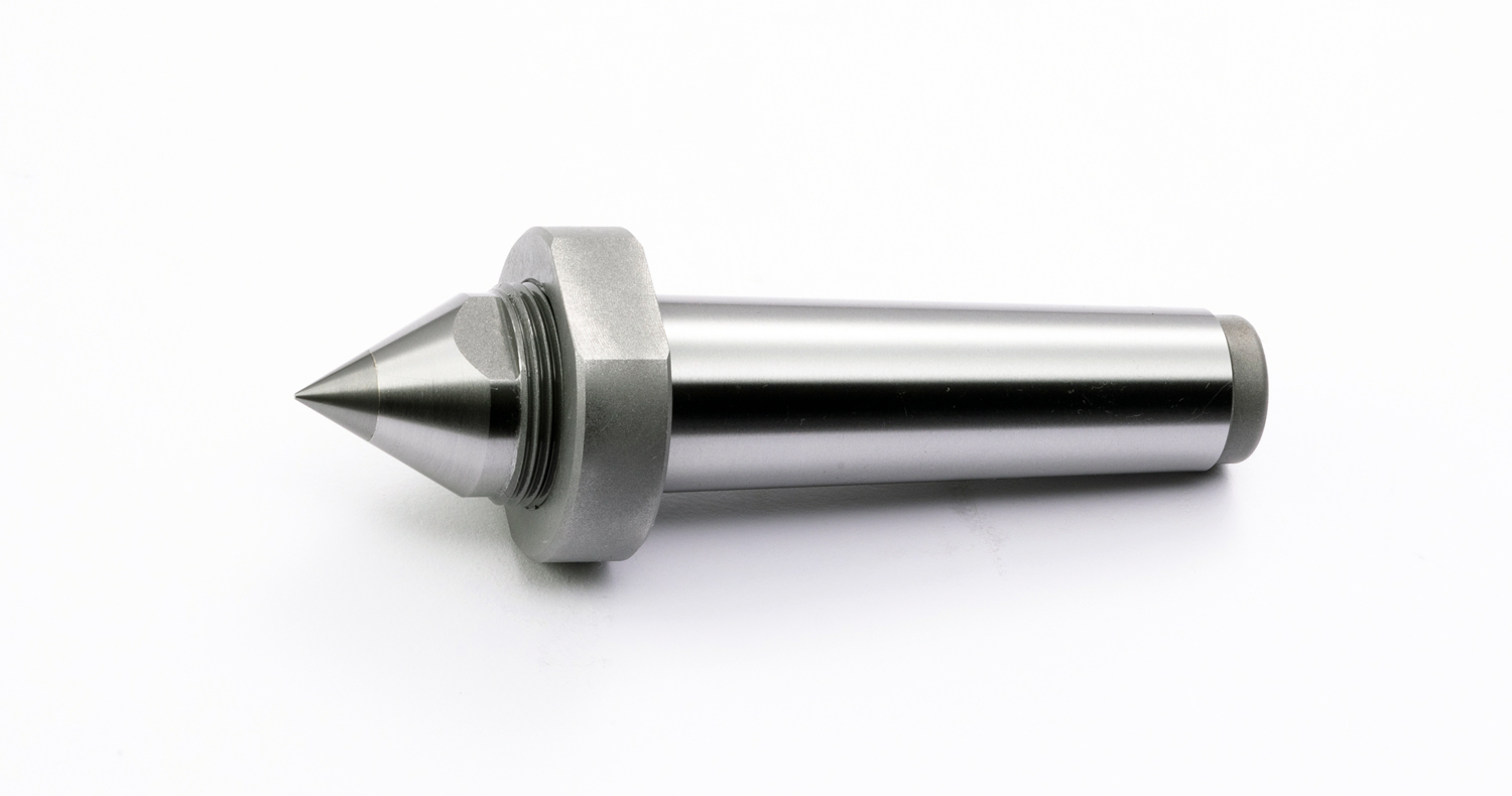
レースセンター
レースセンター
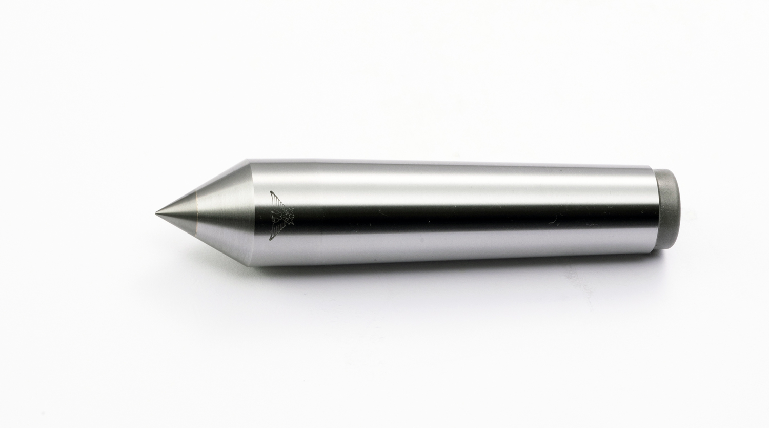
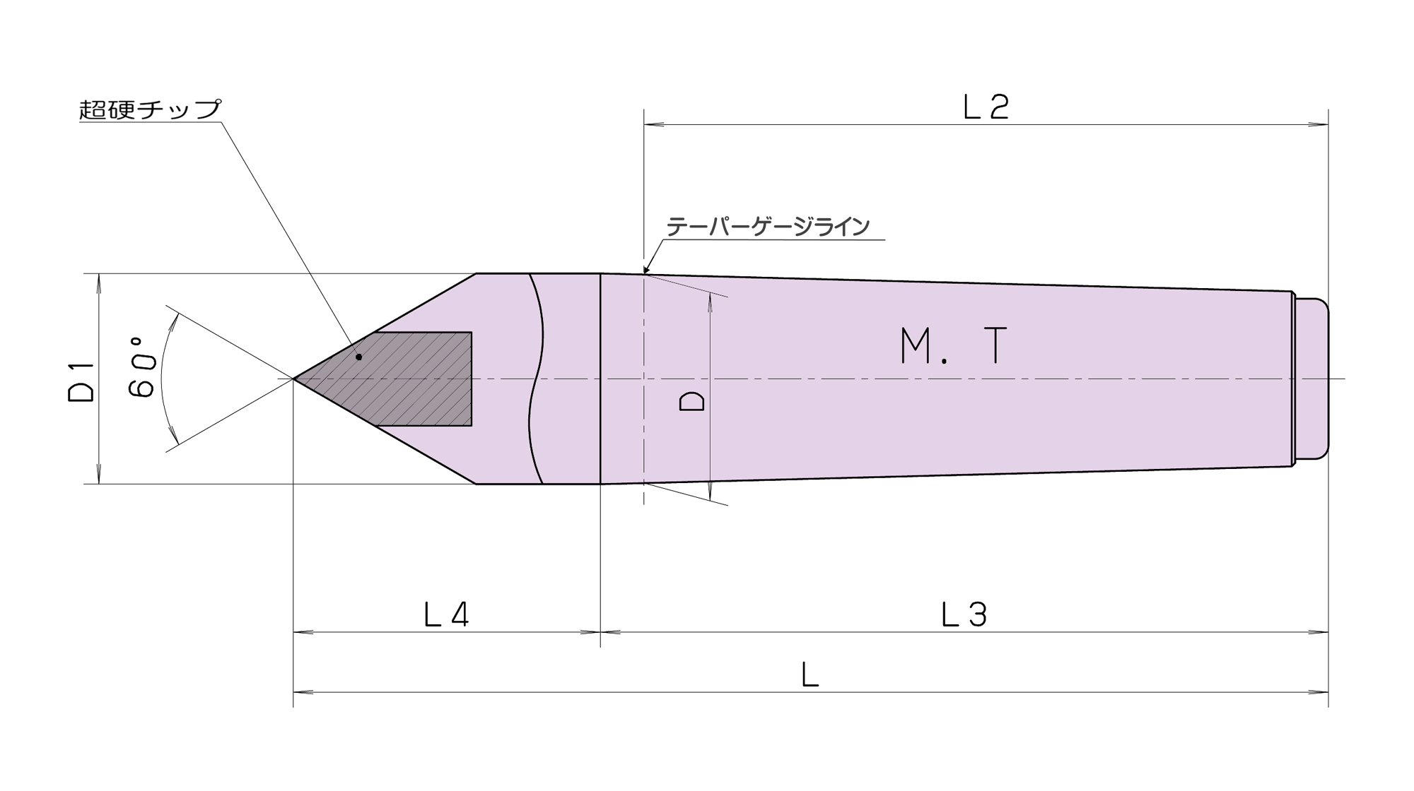
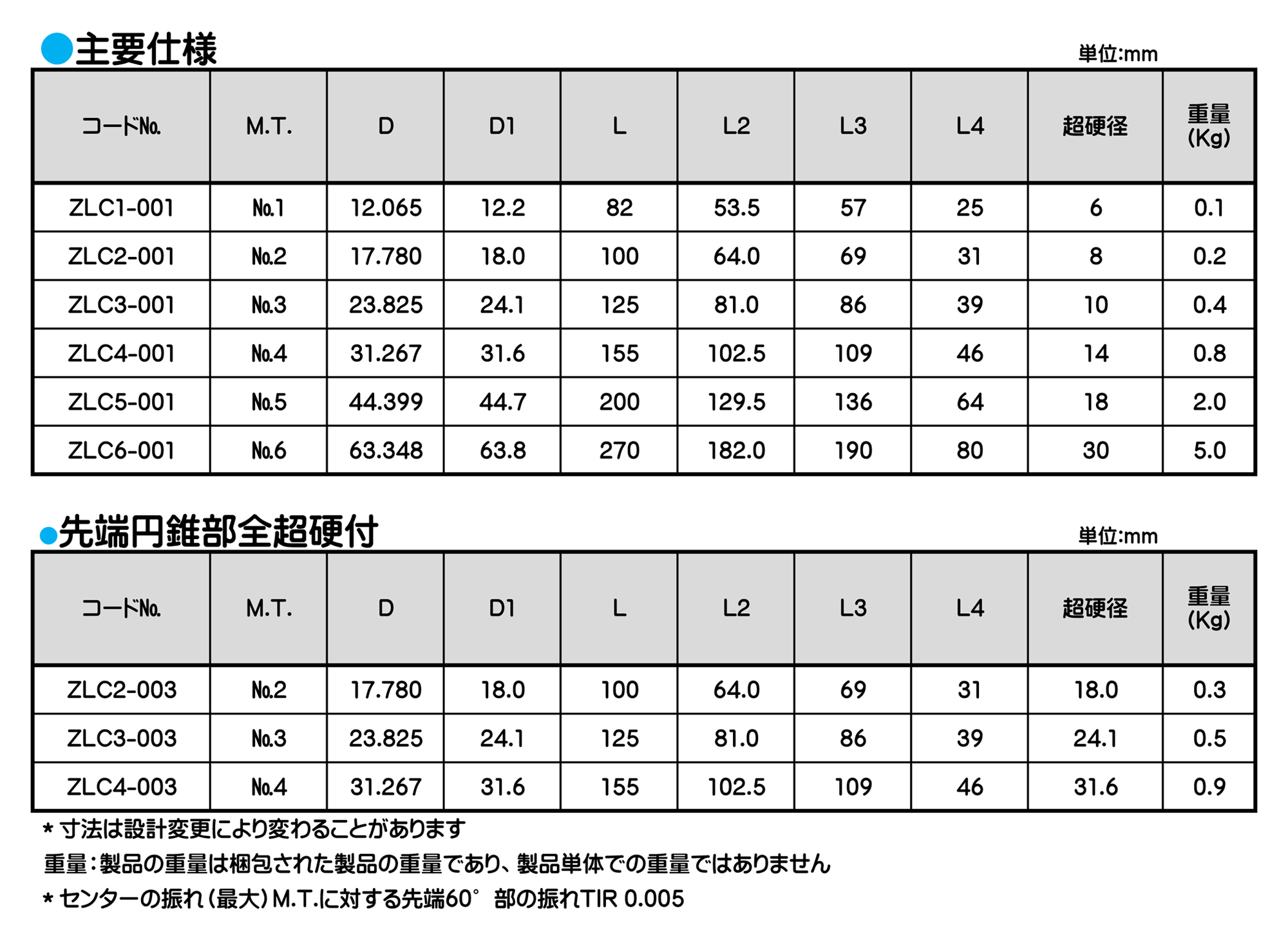
■各種機械、円筒研削盤に使用されます。
■特殊形状チップ付、リング状チップ付、抜きナット付、全長の長いレースセンターの特殊品も受注生産にて製作いたします。
レースセンター
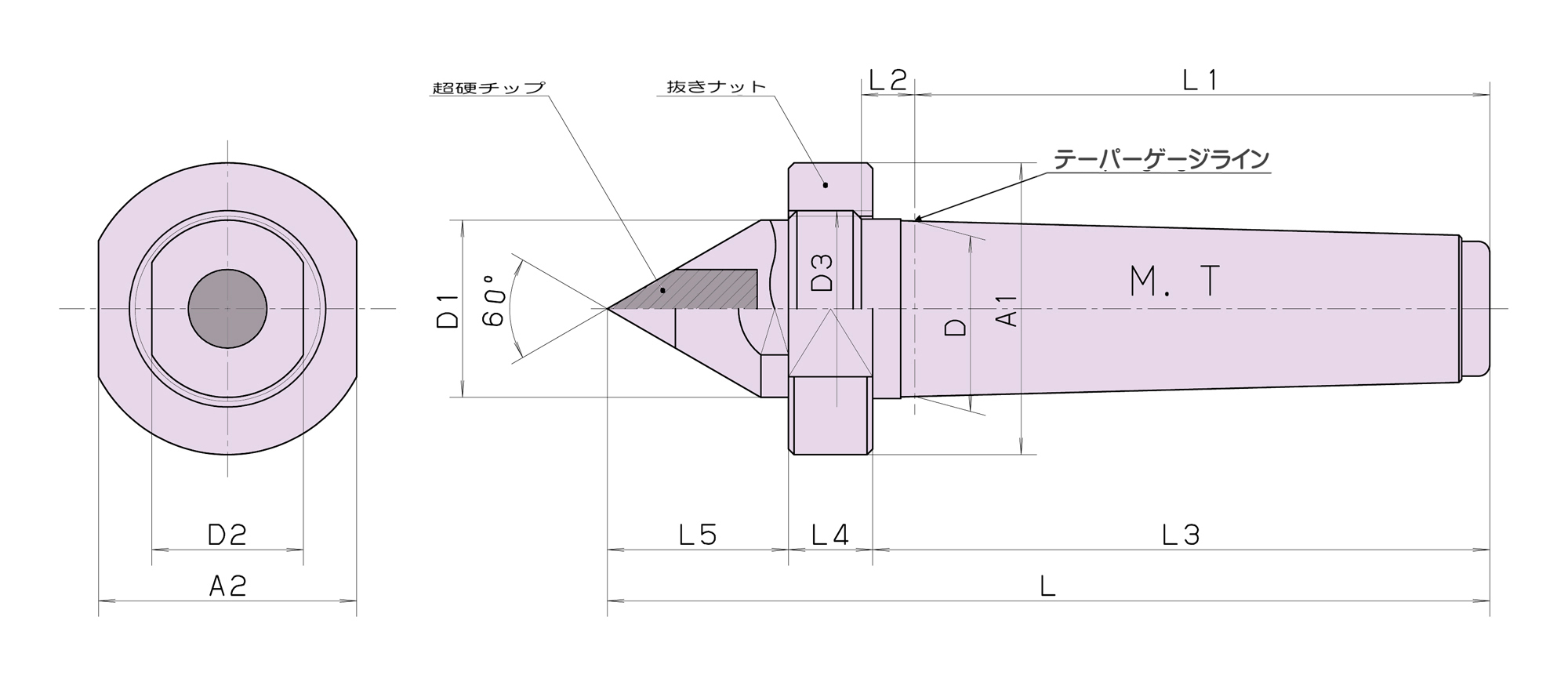
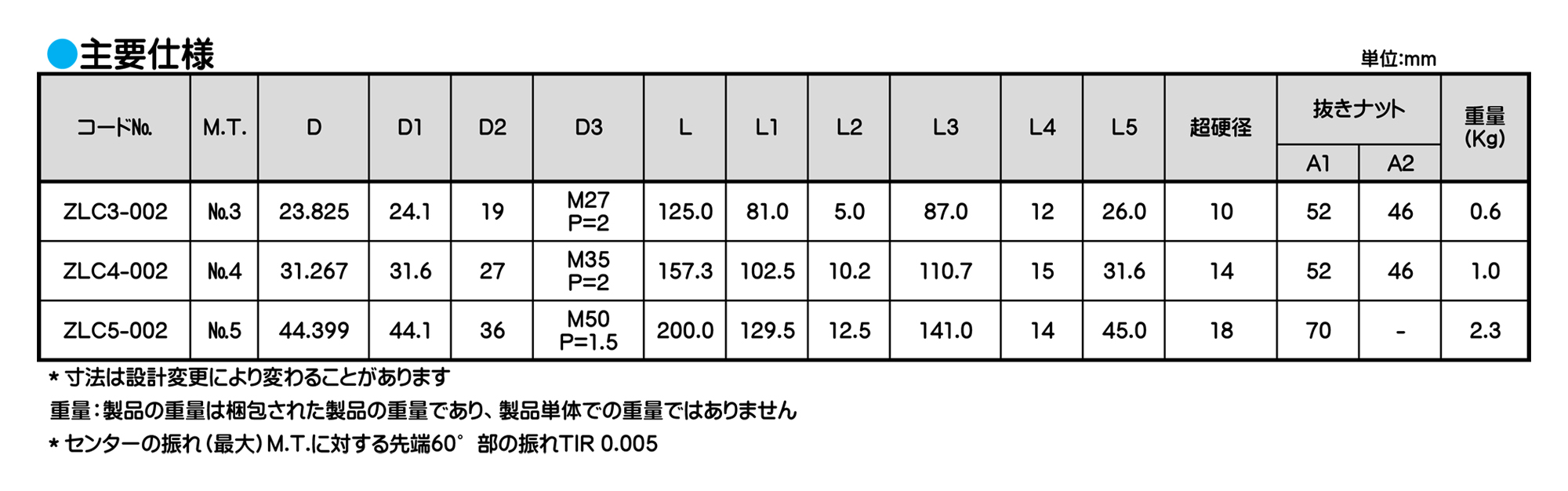
■レースセンターに抜きナットを付けたため、心押台前部より本機の取りはずしが簡単にできます。
■ビルトインタイプの心押台に使用されます。
■特殊形状も別注にて製作します。
■特殊形状を依頼される場合は使用機械メーカー及び機種を知らせてください。
◆ZLC5-002(M.T.5)抜きナット用の引掛けスパナは市販品の70~75用を使用してください。
レースセンター
情報・その他
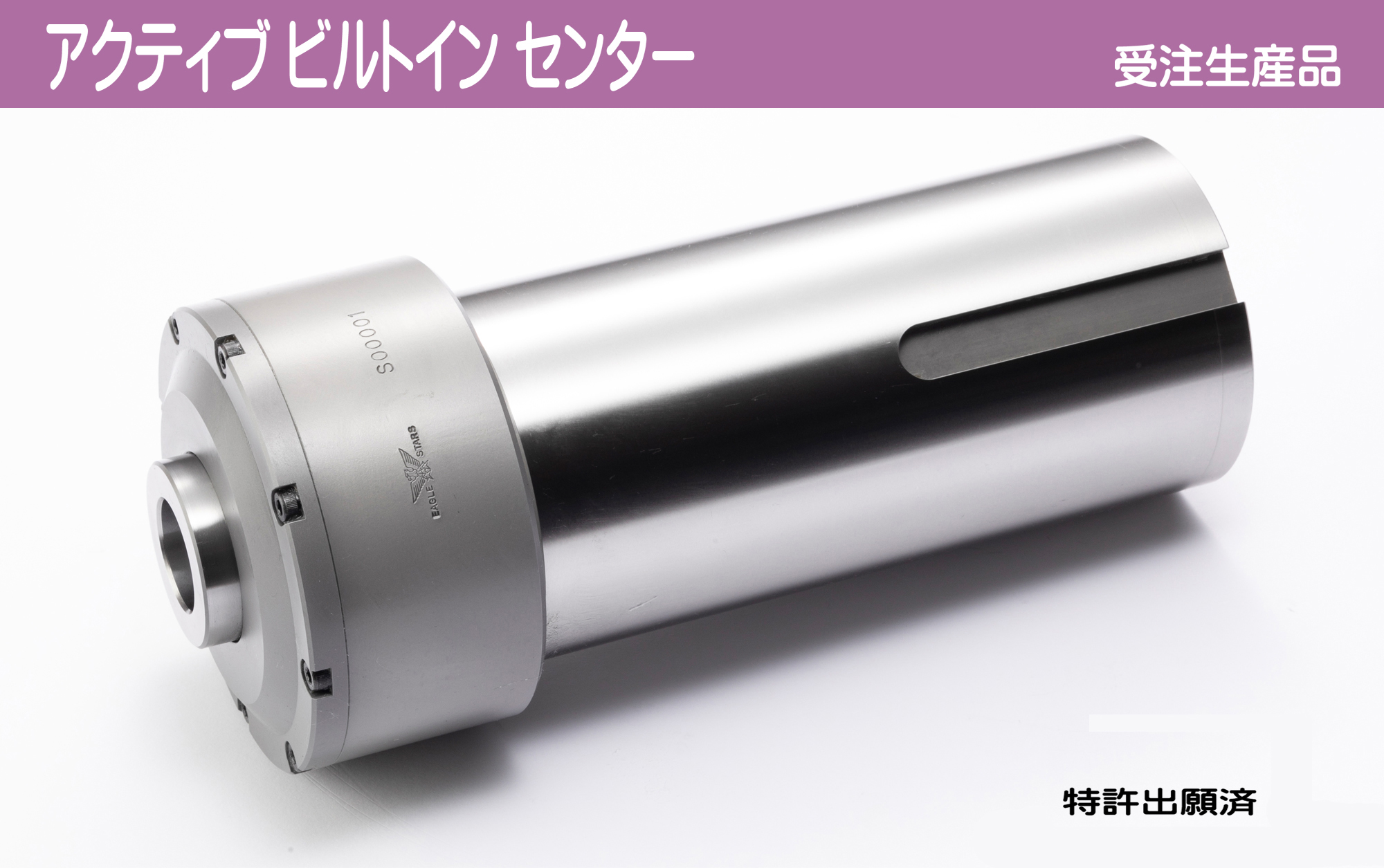
アクティブ ビルトイン センター 【特許出願済】
高剛性を要求する旋盤加工に対応可能な新たなビルトインセンターをセンターメーカーが満を持して製品化。センターメーカーが持つ独自ノウハウを集約したビルトインセンター。
お客様の加工工程がより活動的に、より快適になります。
情報・その他
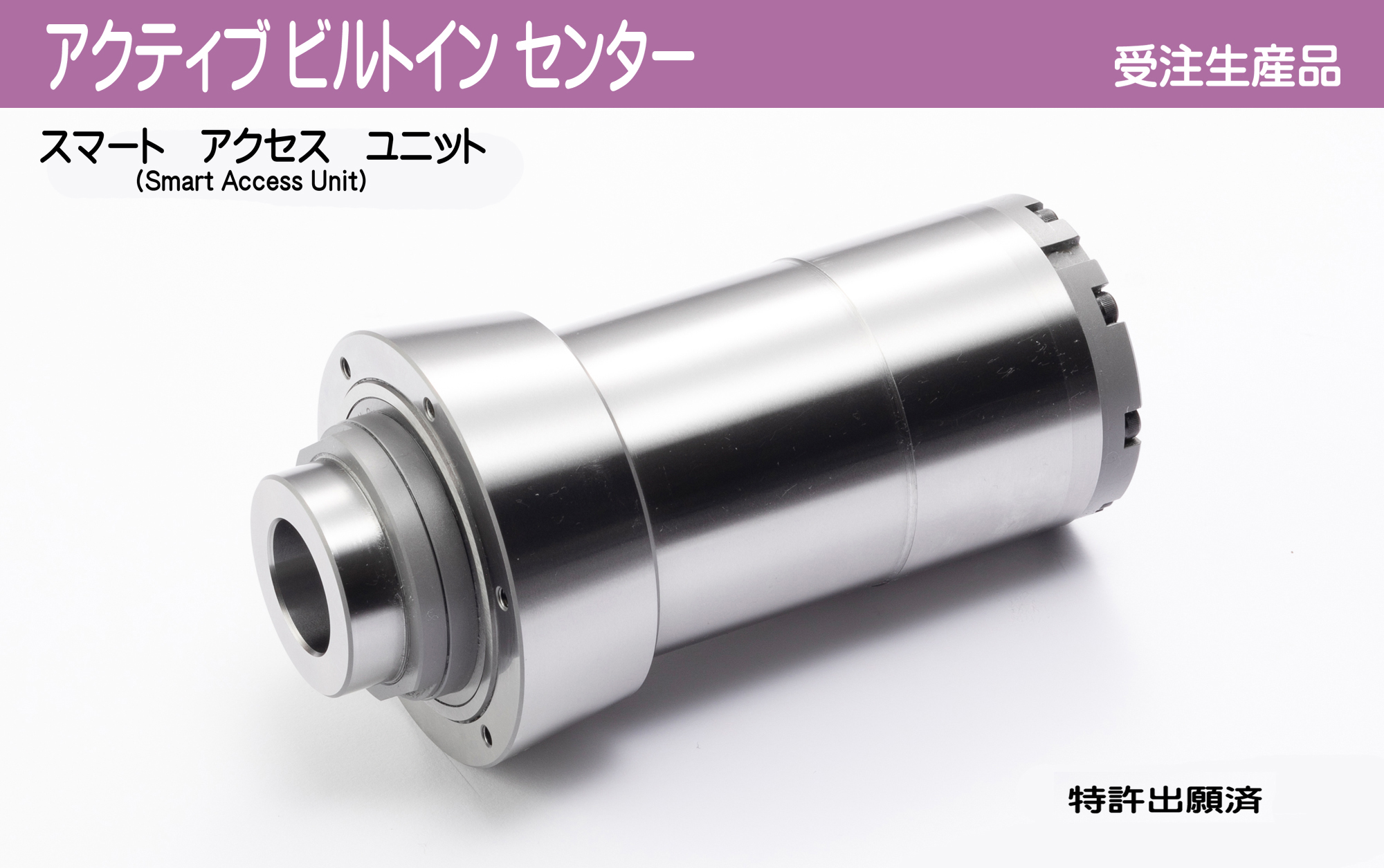
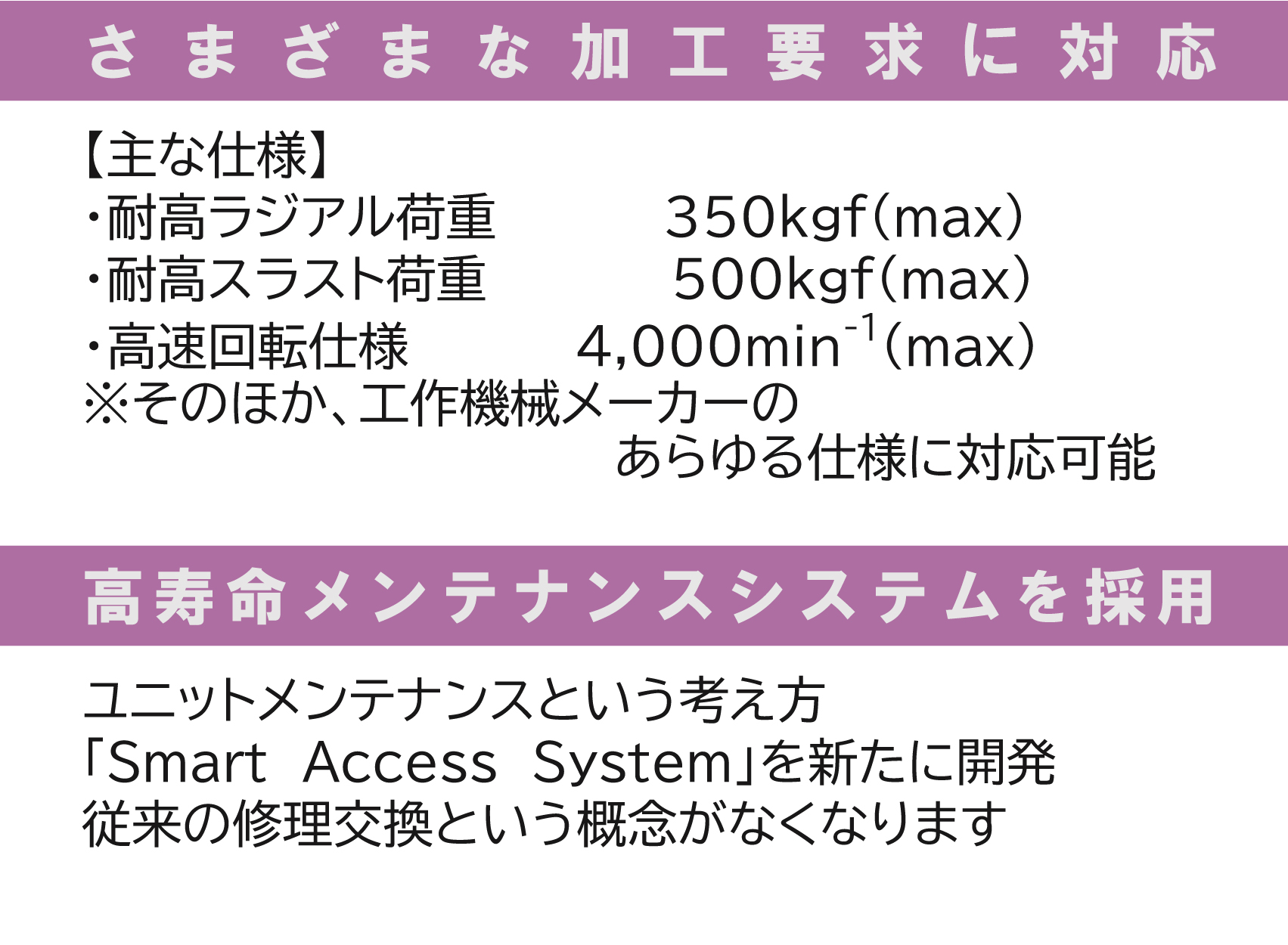
アクティブ ビルトイン センター 交換ユニット 【特許出願済】
Smart Access Systemとは…
ビルトインセンターの平均寿命は約3〜4年。従来はビルトインセンターは修理対応で工作機械メーカーの作業員を必要とする大規模修理が必要です。
このSmart Access Systemは、ビルトインセンターの心臓部である回転ユニットをあたかも回転センターのようにSmartに交換できる画期的なSystemです。このSystemにより、平均交換時間は数時間となり、劇的な工程改善に寄与することができます。
高剛性を要求する旋盤加工に対応可能な新たなビルトインセンターをセンターメーカーが満を持して製品化。センターメーカーが持つ独自ノウハウを集約したビルトインセンター。お客様の加工工程がより活動的に、より快適になります。
情報・その他
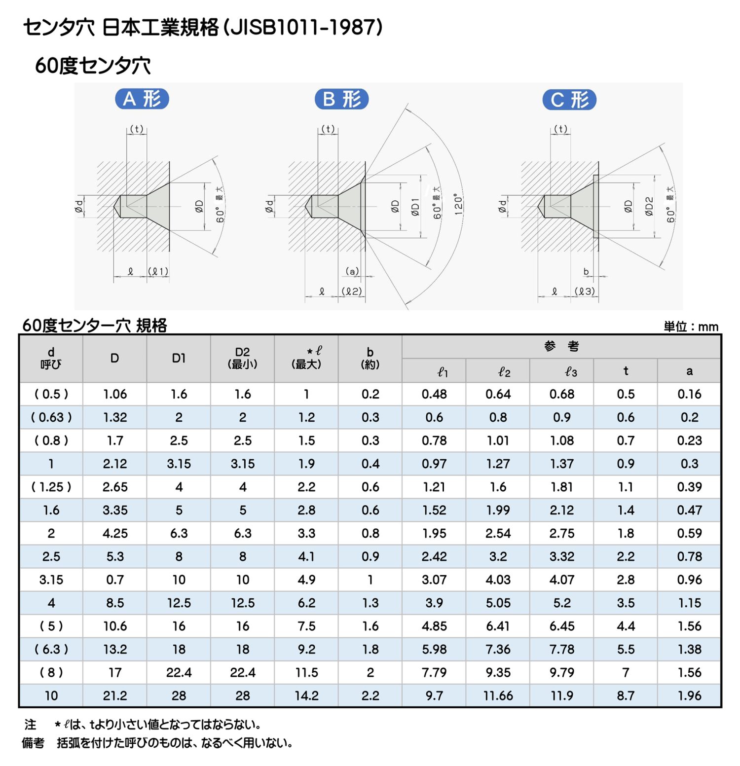
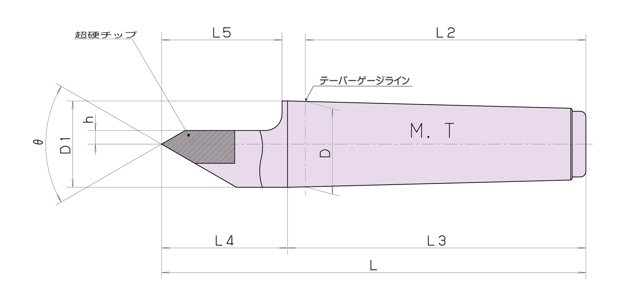
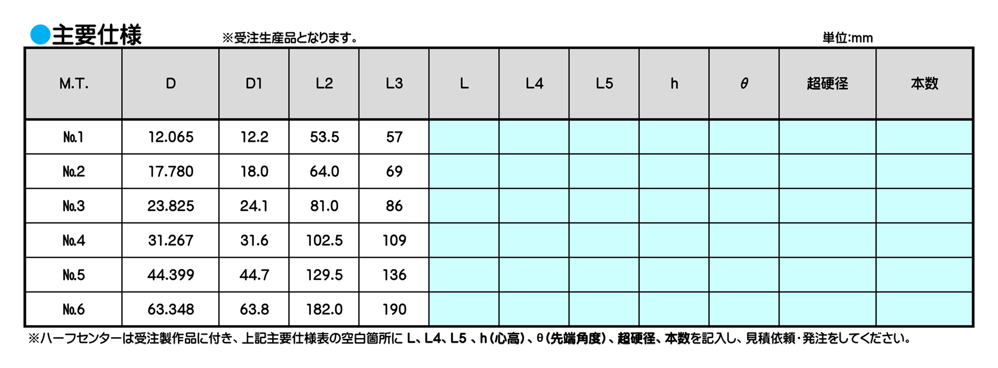
センタ穴は正しい形と寸法に仕上げてください。
ワシ印製品の加工の性能を十分に発揮させるためには、加工物のセンタ穴を正しい形と寸法に仕上げることが必要です。
加工物の寸法に対しセンタ穴の寸法はその使用目的によって限定される場合もありますが、センタ穴寸法についてはJIS規格に必ず合致するよう工作してください。
情報・その他